In connection with the problem of transporting such a bulky unit, it is recommended to pay attention to rational decision nodes connecting wing panels and tail Assembly. For transportation is not so difficult to remove the main landing gear, then the whole model easily folds into a small convenient “bundle”.
Fuselage:
1 — hood (Vileika of fiberglass epoxy resin), 2 — motor mount plastic or metal (finished product), 3 — front frame power (branded plywood, s6, or the bonding of four layers of plywood, s1 ,5 epoxy resin), 4 — strengthening of the weld (pine rack 5×5). 5 — a Board (plywood, s 1,5), 6 — fairing the front (balsa veneer, s2), 7, 8, 10 — the walls of Harrachov (balsa veneer, s3), 9 — fairing average (balsa veneer, s2), 11 — polik (balsa veneer, s3), 12 — prosperous normally open (balsa veneer. s3), 13, 15, 16 — polosamote (balsa veneer, s3), 14 — stringer tail farm top (balsa rail 8×8), 17 — jumper tail locking (balsa), 18 — the cradle of the tail (plywood, s 1,5), 19 — boss tail (balsa), 20 — wall farm tail (balsa veneer, s3), 21, 23 — parts of the frame tail farm (balsa slats 8×8), 22 — stringer tail farm lower (balsa rail 8×8), 24 — hour front Desk (pine rail 15×5), 25 — ears of the mounting strut of the wing (steel sheet, the sl… 1,5), a 26 — stringer subsidiary (pine rack 4×4), 27 bottom plate having a window with a hatch for access to the control equipment (plywood, s 1,5), 28 — bulkhead power (pine lath 20×5), 29 — the walls of the compartment fuel tank (plywood, sl ,5), 30 — sheathing the bow bottom (plywood, sl ,5), 31 — stringers tail fairing (balsa slats 6×6), 32 — edge rear wing (balsa rail), 33 — rib end (plywood, s2), 34 — sheathing panels of the wing (balsa veneer, s2), 35 — additional rib (balsa veneer, s3), 36 — edge of center front (balsa). I — side of the fuel tank (plastic tank volume of approximately 500 cm3), II the location of the receiver, III — the location of the battery, IV — placement of the servos. Bottom right shows the nose of the fuselage. Hatching the designated location, to be pasted on aluminum foil with a thickness of 0.5 mm for protection against damage of paint layers fiberglass engine hood.
Steerable tail wheel:
1 – wheel Ø30, 2 front (steel wire Ø2: damping and spring element shall have four turns), 3 – the bearing rotation stand (brass pipe, after degreasing gluing in the tail boss of the fuselage), 4 – carrier (steel wire Ø1,5: soldering PA choice seam with a coil of thin copper wire). 5 – the clip of the leash (the bending of duralumin sheet, s0,5), 6 – rudder.
Brace wings (four pieces):
1 — termination fuselage (steel wire Ø2), 2 — body brace (pine rack 10×5; profiling to teardrop-shaped cross-section), 3 — termination of the wing (steel wire Ø2; the outside end of the cut thread M2), 4 lock nut M2, 5 — tip steel (finished product to pull the drive wheels).
Details main landing gear:
1 — support front end-to-end (high-quality steel wire Ø4), 2 — bearing rear (steel wire Ø 3), 3 — the clamp on the pillar (steel sheet, s1,5, 4 pieces).
Wing:
1 — ending (balsa veneer, s5), 2 — solitaire (balsa), 3 — the front edge (balsa rail 10x 10), 4 — shelf front edge (balsa rack 10×4), 5 — rib (balsa veneer, s3), 6 — Polonnaruwa (balsa veneer, s3), 7 – a main spar (shelves — pine slats 10×5), 8 — lug mounting brace (beech; on the outside of the frame of the wing by means of a screw to fasten the lug of steel sheet, s1… 1,5), 9 — spar rear (both shelves — pine slats 5×5), 10 — casing of the root partition bilateral (balsa veneer, s2), 11 —trim the root rib (plywood, s1,5), 12 — edge (balsa rail 20×8), 13 — the wall of the end section of the main spar (balsa veneer. s3), 14 — Klondike solitaire spar (balsa), 15 — a wall that is installed to the fixing struts (balsa veneer, s3).
Removable tail:
1 — keel (balsa veneer, s6), 2 — joints, suspension steering, 3 — fairing reinforcement (balsa rail of triangular cross-section 6×6), 4 — stabilizer trim (plywood, s1), 5 —Central part of the frame (balsa veneer, s6), 6 — edge of the stabilizer (balsa slats 15×6), 7, 8 — the elements of the frame (balsa slats 6×3), 9 — solitaire (balsa), 10 — ending (balsa rail 15×6), 11 — edge of the rudder (balsa slats 15×6), 12 — element root rudder (balsa), 13 — bracket connection of the rudder (steel wire 03). Fastening the tail on the frame of the fuselage by means of four nylon screws M5.
The joints of koncowek with the body brace tightly wrap thin nylon thread and impregnate the binding with epoxy. The inner ends of the wire should be bent at a right angle, sharpened and driven into the rail.
Wing area, dm2…………….64
Area becoming, dm2………………. 12
The mass of the model, g 2500— 2600
RKR, g/dm2……………………..39 — 41
Wing profile, %………………. 15
Engine capacity, cm3………………….6,5
In conclusion — interesting information: according to the proposed drawings were collected by reduced modification of the “eagle” under domestic compression motor KMD-2,5. Power circuit of this model is simplified, and the whole structure was reproduced of the available materials — Linden, pine and 3mm plywood with little use of plywood-“graph paper”. Mini”eagle” was also a good flight characteristics, which enabled him faithfully to serve for two years. The wing span was 1600 mm, so the console was made permanent, although the pair of struts are still preserved. In addition, modified the nose of the fuselage, which eliminated the need to manufacture fiberglass hood.
According to the magazine “Eco Model” (Italy)
Recommend to read VELOVIC I must say frankly that for the carriage of baggage, the bike fit a little. Meanwhile we have to do quite often. For example, can not do without Luggage when going on a bike camping... THE LAST FIGHT “TERRIBLE” The Russo-Japanese war, which began with a sudden attack of the Japanese on Port Arthur on the night of 8/9 February 1904 and virtually ended with the defeat of the king's fleet in the... 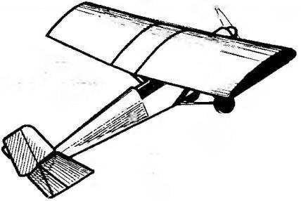
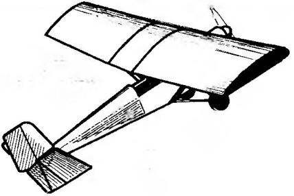 RC model airplane, provided in this publication, it is highly unusual for the national school of design. First of all it is established in accordance with more and more of the fashion for Maxi models (it is appropriate to recall that the rules of competitions of the International Federation of air sports is not the first year there is a subclass supermystery models). In addition, its overall design matches popular today modelers orientation on the old стиль1 when models are more like genuine planes 30 years, rather than a pure sports “shells”.