For cutting sheet blanks of foam is useful to mount a device for thermal cutting, work on which is the hot wire from the faulty electric soldering iron. It provides good quality formed surface of the light varieties of foam without shells and reflow. The food served in cutting the thread through the school a rheostat that allows you to adjust the temperature of its heating.
Machining of workpieces — sharpened knife with a polished blade and skins of medium and small grain pasted on smooth plates. Work slow, smooth movements, moderately pressing the tool. A knife is best to remove thin shavings. The blade should not only move forward but also to continuously move left and right, as if to cut the material. All parts are cut in the direction from the point of fixation.
Wing it vystragivaniem of wedge-shaped foam blanks with subsequent fine-tuning of the profile and surface grinding. Cut off in termostato front plate has a thickness of 7 mm in the region of the rear edge is 2 mm.
After profiling the wing on the ruler are grooves under the “shelf rails”, top and bottom, and by “bracing” if you plan to install them. Preliminary depth of the grooved — edge of a triangular file and needle files, and a final (with the removal of the particles crumble foam) — slozena half cloth.
In the resulting grooves on the glue BF-2 mount “shelf rails” from grass stalks, fixed to the glue pins. The diameter of the stems is about 2-2,5 mm long, the wing tips, they are thinned to 1-1. 5 mm. Front edge is formed by gluing the same stem, back stem with a diameter of about 1 mm.
The stiffness in torsion of consoles provides the cording their macalintal paper on BF-2 or (in its absence) the set of “braces” from the stems of herbs Ø 1 mm. As the elements of the spar, they should reinforce the wing, top and bottom. With “braces” mass of bearing areas is smaller, however, the advantage in rigidity and in appearance remains macalintal paper.
As a set of “skeleton” of the wing, except for the stems of herbs can be applied on the epoxy glued to the surface of the consoles of the thin strips of fiberglass or heavy paper. It should be remembered that the binders nitroosnove can not be used — they will instantly dissolve light foam.
The wedge to the stop fingers at the root of the right wing frame is formed by a planed piece of dense (0.15—0.2 g/cm3 ) foam (of the same material can be manufactured and edges without increasing their stems).
The limb end parts — “ears” — is performed after cutting the grooves with a specified opening angle across consoles. Fixing “ears” with respect to the Central part — on glue BF-2 in front of this lower “shelf longitudinal” incision with a razor blade. The joint reinforce bilateral seam taping double macalintal strip of paper of width about 1 see a More affordable option, but heavier — a strip of thick paper with a scalloped edge on silicate glue.
Throwing (inertia) model of the airframe.
Wing. “Eye” is conventionally deployed to the plane of the drawing. The dotted line shows the installation location of the “struts” of straw when bezobrazna method of construction.
Stabilizer. The dashed line shows the location of the elements of “set” in bezobrazna method of construction. Kiel only has the edging around the loop.
The front part of the fuselage:
1 — plate (dense foam), 2 — pad (Linden), 3 — tail boom (easy foam), 4 — stringers (straw).
Cross-section of the wing through the Central part (top) and at the place of transition to the “lugs” (bottom).
Assembly of the fuselage.
A device for thermal cutting of polystyrene:
1 — pin 2 — screw, remote pads, 3 — cutting the heating element, 4 — base, 5 — tension spring, 6 — wire power supply.
The fuselage is assembled from the bow (dense foam with a thickness of 5 mm) and tail boom (light foam of the same thickness). The beam is reinforced with stems maximum Ø 2 mm, decreasing to 1 mm to the tail. The junction of the fuselage is reinforced on both sides of the unit (the lining of the phony veneer of a thickness of 0.7 mm, a width of 9-10 mm. Height of the tail boom at its rear edge is 4 mm.
The stiffness of a beam in torsion will increase the cording of mcalenney paper. However, without it, the fuselage is extremely durable — he remained free of damage even after you start using the catapult. However, in this embodiment, the beam there is a high risk strains, which may require additional adjustment. Therefore, if mcalenney no paper, increase torsional rigidity by tying the spiral thread on the glue in two opposite directions, apply diagonal stripes of thick paper or embed in the foam struts from thin stems.
Stabilizer the most successful design — foam. Procurement of plate thickness of 1 mm, fringed around the perimeter of stems of appropriate diameter and glued macalintal paper gives the optimum combination of rigidity and good appearance.
When an individual building microplanar more affordable (but more difficult) is “stacked” design. When the thickness of the foam in the middle about 2 mm with decreasing towards the ends up to 1 mm stabilizer with herbal spars, “braces” and “ribs” will be easier covered with paper. Bent when adjusting the model part of the horizontal tail is formed by the border of the corresponding plot stems Ø 1 mm, followed by cutting of the end edges with a razor blade.
Keel manufacturing technology, materials and possible design options similar to stabilizer. In all cases for elements of a set of feathers used straw maximum Ø of 1 mm.
Assembly begins with gluing the wing to the fuselage, it is better for the epoxy resin with the strengthening of the joint with a thin fiberglass strip which goes on the taping the center seam of the wing. Substitute fiberglass may be heavy paper. The stabilizer and fin are mounted on the beam using the “corners” of mcalenney or regular thin paper.
At the time of adjustment microplanar the rigidity of the tail in General can be improved by installation of temporary braces or herbal cotton stretch between the tip of the stabilizer and fin, as well as the bottom plane of the fuselage. Last valid system to enhance the stretch, similar to that used on the indoor models.
Achieve the desired alignment, loading the nose of the fuselage with pieces of lead, winding the wire or other arbitrary method. For launches from the catapult at the bottom of the nose, in a sealed wood block mounted starter wire hook. Mass of the main components of the airframe during various manufacturing methods shown in the table.
The boundary values of-flight mass fully equipped models with the download of the forward fuselage balance weight comprises:
— in the manufacture of main parts without covering — 14 g,
— in the manufacture of a cording paper 22 g. Pre-adjustment is carried out mainly as described in the article “the Rise with hands” (see “M-K” № 7, 1985). Only the “eye” for the sake of simplicity zauzhivaetsya and shortened.
Propelling the airframe of the proposed design is highly popular among our modelers, especially beginners. The flights are spectacular, as when the riders hand, and when ejection or start planning with the hills.
It should be noted that the increase in mass to match the balsa model-the prototype can significantly improve the surface quality of bearing areas and increase the planning time. This is achieved by re-pasting macalintal paper with the subsequent polishing and varnishing.
Interest in throwing gliders justified not only by availability and ease of manufacture. It is also important that such apparatus can be run (and carry with them the competition) on sites not suitable for testing any other models.
The mass of the model elements of the airframe in various designs, g
Version
Wing Tail boom Tail Assembly Without fining macalintal paper without diagonal stiffeners
5 — 5,4 1,8 0,75* With the wrapping paper without diagonal elements 7,8 — 8,4 2,3 — 2,5 1,5 * Without wrapping paper, with diagonal elements
5,8 — 7,3 — 1,5 **
* The stabilizer and fin thickness of 1 mm.
** Keel thickness of 1 mm, stabilizer stacked.
V. MATHIS, Votkinsk
Recommend to read SMALL, BUT PERFECTLY FORMED! Walk-behind self-built eager to make the most versatile. This is understandable: it has to perform a variety of agricultural operations. However, to create a design that is most optimal... Electronic thermometer This device can quickly and accurately measure, for example, the temperature of a human body, water, and air. An electronic thermometer is needed by agricultural workers to determine the... 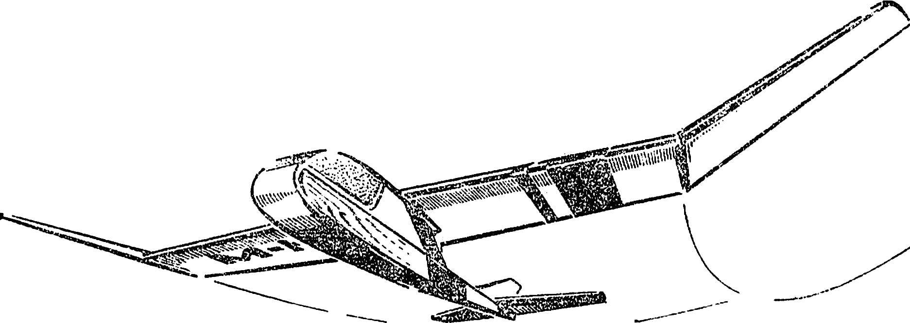
 Can you name at least one model class that is really available to everyone? Until recently the answer to this question could only be unequivocal: no.