The Autonomous device; “powered” from the battery or three elements of type AAA, total with a constant voltage of 4.5 V and remains operational when the voltage drops to 2.7 V, and with increasing voltage to 6 V. don’t recommend to power it from stationary, even a very stable voltage source, because the meaning of the operation of the device once lost – there are wires and vibrating alarm to hide from prying eyes.
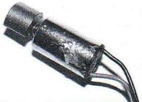
Vibrating alarm (electric motor with eccentric) taken from a cell phone, Nокіа 3310.
Electric motor with an eccentric, taken from cell phone NOKIA 3310 for the manufacture of vibrating alarm
The electrical circuit vibrosignals device
Electric motor (no markings) works well at a voltage of 2.2 – 3.8 V (with a voltage higher than the 3.8 has not been tested). At a voltage of 3.3 V, consumes 24 mA.
The circuit elements are mounted on a small Board. It is necessary to ensure that the length of conductors and findings of the elements was minimal (to reduce interference, leading to possibilities of false positives), as well as to provide security measures for field-effect transistor, eliminating the influence of static electricity. For this to be grounded soldering iron tip, low power soldering iron (no excess application on a grounded anti-static wrist strap).
The quality of the transformer T1 is applied a popular matching ST-1A with three windings that were previously equipped with a portable transistor radios already out of fashion after extensive development of the FM broadcast band. It is perfect for this device (the development was created under ARTICLE 1A).
As transistor /T2 you can use any low-power transistor n-p-n conduction with a collector current of at least 50mA.
FET VT1 assembled high-frequency generator, the frequency of which will vary markedly when approaching A person, animal, or large object, absorbing the RF oscillations. Changes in the frequency can be locked on an oscilloscope with a high pedantry entrance. Schematically, the resistor R2 is connected in parallel to the winding feedback and also (as a minor item relative to the capacitor C2) adjusts the sensitivity of the site.
Circuit Board, vibrator M1, the switch S1 and the batteries are placed in a small unshielded dielectric body, the size of a soap dish outside of the case is displayed only And antenna – cut the flexible insulated wire of length 50 cm
The current consumed by the circuit in standby mode is extremely low, less than 5 mA, which provides (established practice) month of continuous operation.
The device is actuated at the moment when someone gets too close to the antenna or touch it. The sensitivity of the device is that the alarm will work even if the “cracker” will wear leather or rubber gloves. Vibrating alarm M1 will be turned on as long as the device takes out a short-term disconnection of contacts of the switch S1.
The capacity of a non-polar capacitor C2, if necessary, select a better alignment with the length and location of the antenna.
Oxide capacitor C1 is set to the stability of the power supply; if the voltage is less than 4, it “pulls” the scheme ensures its operation.
The practice established that this security system works reliably in combination with the wooden drawers of the table (any non-conductive materials) and set on the table a conductive metallic locks and latches. Unfortunately, metal drawers and doors, “screening” is low power and overloading the generator, do not provide the correct circuit operation.
The principle of operation
In the normal (standby) mode upon power-up the generator on field-effect transistor in combination with the excited winding of T1 generates oscillations of the RF. Output from the secondary winding (right scheme) oscillations rectified by diode VD1, and this positive potential keeps the transistor VT2 is open. Resistor R3 limiting the current in the circuit of transistor VT2, does not allow the transistor to overheat and fail. Collector-emitter voltage (the voltage drop across the junction) on-state transistor is practically zero; this, in turn, provides a constantly closed state of the thyristor /S1 (thyristor /S1 are shunted by an open transistor VT2).
Antenna loads (when the object is approaching) high frequency generator; its generation, broken in the result feed is interrupted and the opening of the positive voltage to the base of VT2, it closes and the thyristor, on the contrary, is opened by current through the resistor R3 and M1 vibrate. Since the thyristor “energized” from DC, he until then will remain open until you break the chain of his power, or at least short-term, not de-energize the circuit.
Recommend to read HEADSETS BOARD Special cheap and practical furniture for garden house is not yet sold, so usually there dumped all the junk. But what looked good once in a city apartment, in a small country the room... COAT OVEN Older homes still sometimes there are amazingly cozy and beautiful tiled stoves. Alas, today, like the furnace heating, the tiles are fading. And they can be found only as a piece of... 

