The model of the aircar, under the KMD engine with pusher propeller:
1 — nose wheel fairing, 2 — front, 3 — bottom case, 4 — motor, 5 — upper body, 6 — motor, 7 — chef, 8 — rear wheel fairing, 9 — stand back, 10 — cord strap, 11 inlet, 12 — fairing cylinder head, 13 — needle adjust the fuel mixture.
Total failure has forced them to take another look at the seemingly perfect scheme. And then there’s group discovered that a similar effect “made up” and their opponents, which also attracted a journal publication. You know how quickly pass sentence modelers failed, in their opinion, the designs here were added, and sverhkategorijnost judgments inherent in boys.
Method not allowed the compensation of gyroscopic torque (a) using a fixed and acceptable, but undesirable method (B) with the use of lightweight propeller, the removal of the rear walls of the back and inclination of the axis of thrust of the screw down.
Scheme cars are designed considering the influence of gyroscopic moment and providing compression of the bow wheels or skates to the track.
However, the story ended quite suddenly. Ustinov a bit, we decided to find out why seemingly insignificant transition to the class of AM-2 gave such an unexpected effect. And… couldn’t find anything even close to solving the problem! However, new ideas to save so winning in aerodynamics scheme due to the pressure front of a small wing, to load the bow of the model to include the axis of the rear wheels farther from the center of gravity. However these were half-measures, and to take model with the “flight” instincts, it seemed scary. But, looking collection of publications in search of ideas new technology, someone timidly said, “Here refers to some sort of gyroscopic the moment. And what is it?” Uncertain observation was the clue to the problem! And it is not surprising that she came across by chance: the effect of gyroscopic moment the vast majority of avtomodelistov don’t think. In the literature mention of this factor are extremely rare, and with specific values, you can meet only in one article (“M-K” № 7, 1982, article “spinning Top on a rope”). Therefore, even experienced athletes could not explain the unexpected behavior of the aircar.
Now it has become clear that on the specific machine-“know how” offered by the journal, the effect of gyroscopic moment was useful in its low value — parasgraphs strut front skate, and snowmobile were softer. However, the cost to increase the speed of the engine speed or the diameter and mass of the propeller, as the use was turned into an extraordinary harm. It’s good that the model AC-1 we have not tried glass fibre laminate propeller! With him, two times heavier than modified nylon, already the first machine could also escape into the air. And then nothing would have forced the boys to get into the theory would not help them to learn that even something as seemingly serpastye externally of the model subject in motion many “adult” technical laws. And only their whole complex, with the exception of the one unknown of the law leads to erroneous judgments and conclusions!
So now we can design the model according to the precise requirements of racing. For the class of AM-2 for pressing the nose wheel will only need to move the cord strap to the other side of the case or change the direction of rotation of the propeller (by the way, it is possible to recommend for “lorry” when using heavy propellers complete with perforirovannykh high-speed engines). We understand that the packaging of the wing would be incorrect. In case of accidental lifting of the nose only 10°-15° this wing would be to create positive buoyancy. And given the constancy of the gyroscopic moment in this range of angles of takeoff of the model would be guaranteed. Download of the nose is undesirable because of the growth of the losses of the heavier rolling of the apparatus (according to our observations, the relief of the aircar is more important than racing snowmobiles). The only possibility to affect the magnitude of gyroscopic the moment without compromising speed model — the use of light-weight wooden propellers.
The design of the model:
1 — fairing front wheels, 2 — wheel Assembly, 3 — fork, 4 — stand, 5 — the original contour of the body, 6 — lower part of the body with modified contours, 7, “fungus”, 8 — motor, 9 — upper housing, 10 — fuel tank 11 — tube refills, 12 — engine KMD, 13 — end “web”, 14 — spinner, 15 — fairing, 16 — rear rack, 17 — feed hose.
In our case the layout of micromachines is that the gyroscopic moment will only push the nose wheel to the track. This eliminates the need to re-aim when you replace, for example, wooden propeller on the glass fibre laminate gives the possibility to shift the axis of the rear wheels almost at the center of gravity. Latest sustainability models kartodromo any quality.
Conditions for the occurrence of “pitching” moment. Black arrows show the direction of travel of the model and rotation of the propeller.
General diagram of the machine remained unchanged.
Revision Zolotnik wall of the crankcase.
New system of fuel delivery to the carburetor.
In connection with increased in comparison with the prototype weighing machine front rear wheels — maximum rigidity. After all, to provide ultra-mild “suspension” as “lorry”, would enormously increase the scope of the strut-spring. Sealed wheels: steel discs (their inner plane have a lot of small circumferential grooves) is tightly clamped ring”tire” sheet of hard rubber with a thickness of 1-1,5 mm discs are Fastened by caulking tool resembling a Phillips head screwdriver. Only after that the Central hole is brought up to Ø 4 mm with a pitch and conductor.
A pair of front wheels mounted on the axis of the screw M3 Assembly in the spacer tube-bearing, solid brass Ø 4X0,5 or the same piece of steel. Its length is selected so that after tightening the thread of the wheel rotated freely, but without a large axial backlash. The plug and leg wire OVS Ø 2 mm, the parts are held together with pre-soldered winding joints of thin copper wire. Two steel wires are also soldered to the top of the rack. After winding the solder joints with thread adhesive formed well prepared for the installation of the wooden parts of the surface.
The machine frame is represented by three parts: aluminum engine mount cut out of sheet with a thickness of 5 mm, and two wooden parts. In connection with the increased dimensions of the tank under the engine working volume of 2.5 cm3 , a high level of vibrations and the requirements of the operation of the feed system under pressure from spectacular tank-lantern had to be abandoned in favor of classic, brazed tin-plated tin. The latter is suspended in the neck of the motor screw M2,5 with the use of rubber washers gaskets. Wooden parts are cut from basswood medium density and off in a known manner.
High calorific engine KMD and summer conditions are forced to pay special attention to the cooling. To improve the heat sink with sufficient uniformity around the circumference of the cylinder is possible by the circuit shown in the drawings. The front of the shirt is blown intensively directed stream, side — air flowing down from the fairing and rear — only, due to the turbulence. From Carter heat is removed further through a metal engine mount and cylinder head — through the rear wheels. The latter should be freely secured to the shirt sleeve, on your place is fixed with long screws M3 included in the normal socket of the crankcase for mounting the shirt.
Refinement of the engine is conducted in full compliance with the recommendations of the article “Sprinters ice kartodromo” (M-” No. 9 and 12 in 1987). In addition, we used the experience of model aircraft and modified the slide wall of the housing. With its 90° turn, apparently, improves the lubrication of crank pin crankshaft and filling the volume of the crankcase with a fresh mixture. The increase in speed is very noticeable, and the mode of operation becomes light, with no signs of displacement.
Power system with fuel under pressure, which allows to use wide-open diffusers carb. The nozzle ring type believe the least successful of the possible options with a relatively low consumption of compression engines and large centrifugal loads. The most progressive scheme is put fuel in the carb through the tube, the cut which ends at the axis of the air flow. To do it on KMD can sapaw three hole standard nozzle rassverlit fourth and cut into it the threads of the M2 and installing a new pipe-the nozzle from the threaded shank. After Assembly regular turn nozzle and clamp. A similar scheme can be used with the use of a tubular diffuser.
The direction of rotation of the crankshaft KMD upheld. In the cheek of the spool sawn through a new hole at 90° to the normal, which is caused by the rotation of the wall at the same angle. The change of direction of the motor is junk — worse conditions of filling of the crankcase with a fresh mixture and pass the mixture into the cylinder.
N. NIKOLAEV
Recommend to read FUEL — CO2 On 37-th Moscow city competition of young men in the micro models, held at the tennis court "Dynamo", the attention of fans and athletes drew suddenly appeared in the air brightly... AREA WITH A WATERFALL… In addition to the traditional garden chores gardeners are more inclined today to use their sites primarily for relaxation, socializing with friends and nature. Accordingly, for these... 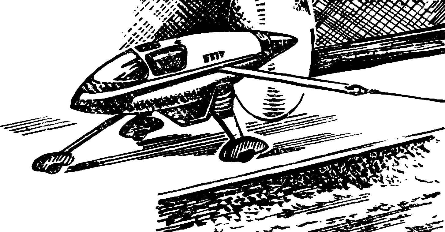
 When our boys faced the problem of choosing equipment for the new sports season were not differences. All who are engaged in class models AM 1 and AM 2, stopped, as agreed, the scheme proposed with the article “New ice season” (see “M-K” № 3, 1986). And it is clear. Usual off the aeromobile aircraft type with stabilizers a little “boring”, and are given drawings of the machine, more like a real flying car of the future than clean special sports equipment. But most importantly — the benefits of aerodynamics microsony with pusher propeller seemed indisputable. Really liked the logic of their design: improvement of the apparatus is achieved a simplification. This not only reduced aerodynamic resistance to the ideal minimum, but also greatly facilitates the work on the model. And this is when it is very effective.