The motor unit includes a housing and a container. The case is made of thick paper and has a length of 175 mm. is spiral Wrapped on the mandrel with a diameter of 13.5 mm. installed Front fairing from balsa and rear fixed sleeve length 63 mm with a recess for the brake band. With the opposite from the recess side glued blank, in the face of which is pressed a steel pin with a diameter of 1.5 mm.
The container (tube length 105 mm) is molded from fiberglass. One end is made a longitudinal cut with a width of 5 mm and a length of 45 mm. To the other over the neck glued to the pylon. Here is the same, but on the other side of the container, glued the retainer MRD, bent from a steel wire of 0.5 mm. 0 Pilon profiled balsa plate thickness 7 mm. In pylon mounted a spring and a notched lever pusher carved from basswood.
The housing and the container are connected by a strong thread length of 300 mm. In place of its attachment on the housing is glued and thread recovery system (the brake band). The guide tubes two. Their length of 15 mm and a diameter of 4.5 mm. they are Located on top, one for the body and container.
The launch mass of the rocket is about 30 g, and the actual planning part — 10 Model off the engine “Delta” of the Czech and Slovak designer and Modeler I. Taborskeho.
Preparation of the rocket for launch is as follows. In the container insert of MRD and fixed with the holder. In the recess of the sleeve body placed in a rolled tube and the brake band is worn on the sleeve of the container, thus connecting the housing with the container. The drive lever is inserted into the front cutout of the top panel of the fuselage. In the final phase of this operation, the pin lock is inserted into a corresponding hole of the forward fuselage. The pin serves as a castle that protects from the impacting force of the ejector spring.
Drive in the moment of connection of the parts of the model begins to push on the pushrod, which, in turn, transmits the force on the flap brackets, and they are slightly deflected upwards. Thus on takeoff the curvature of the airfoil decreases.
The brake plate is pressed against the side of the fuselage and tied off with thread. Then set the fuse time limit of planning. The placement of the wick in order to avoid burnout of the fuselage paste over a strip of foil.
After the launch and burnout of the fuel is triggered expelling charge mrad. Almost simultaneously (delay not recorded visually) occurs as the separation of body and container, and the ejection of the entire propulsion unit elasticity of an ejector spring. At the same time the flaps of the glider under the action of elastic bands are deflected to the lower position. The curvature of the airfoil increases, which is necessary for improvement of gliding properties of the model (compared to “flat” wing descending from the same height, much more). The glider continues to fly, and the motor unit disassembled lands on the brake band.
In the final phase of the flight triggers a forced landing: the wick burns through the locking thread, and the brake flap is deflected to the side. Model the result becomes unstable in the spiral mode of descent and safely, without damage lands.
V. ROZHKOV
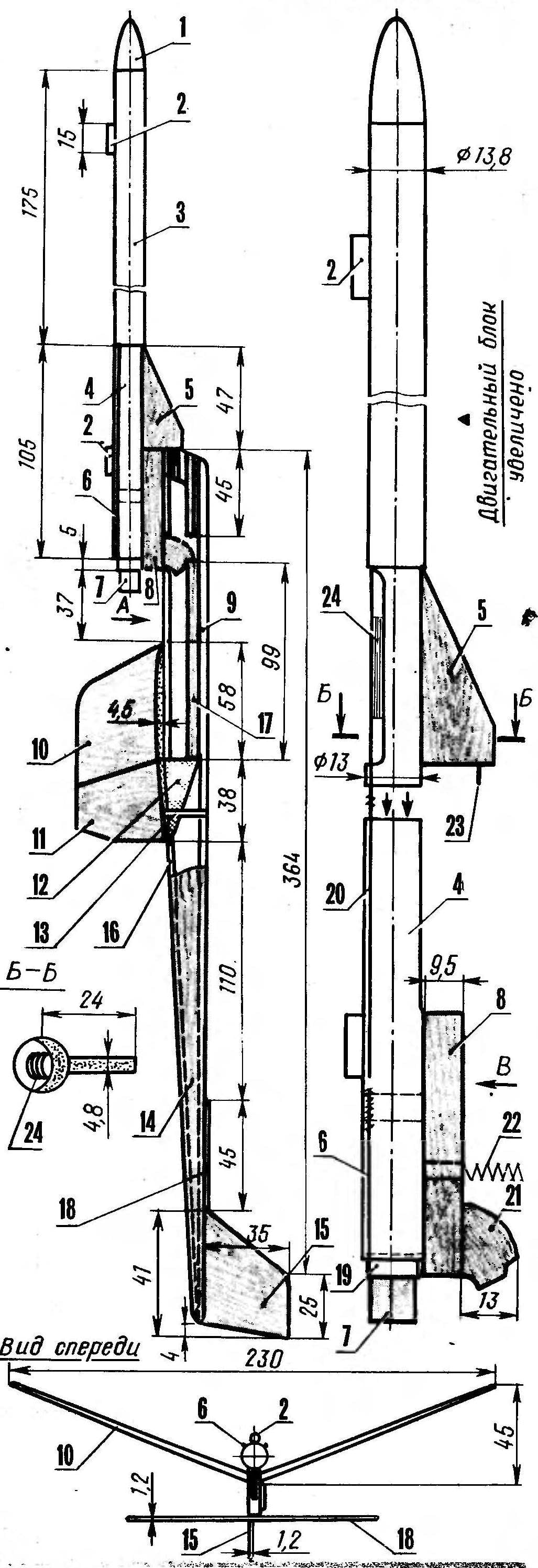
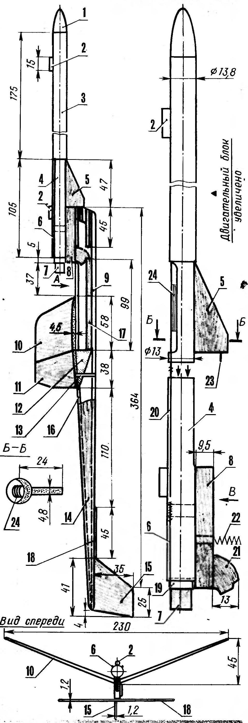 Held in the fall of 1991, sports bilateral meeting of American and Soviet missile-modelers winner in the class S4B was Robert Park, a native of the state of California. His rocket plane “Hummingbird” for all the apparent simplicity has a number of original technical solutions. One of them is separating the propulsion unit. Second — change the camber of the wing by the deflection of the flaps.