 This model was designed by students of Victor Pisarev, Alexei Knizhnikov and Nikita Novikov. They built it in the ship laboratory of the Moscow city Palace of pioneers. High speed of -10 m/s, stability on the course and high bench evaluation allowed the boys to take first place in the class of civil courts and become the champion of Moscow among younger students. The model was shown at the international exhibitions of technical creativity of schoolchildren in the United States and Canada. Given its description.
The case of the model (Fig. 1) from fiberglass. Before we proceed to its manufacture, make of basswood or other soft wood the fool (punch) size 890X120X80 mm. Using a theoretical drawing (Fig. 2), handle bar first outer contours “side”, and “semi-range”, and then templates of the frames. Make them out of plywood with a thickness of 3 mm, using a theoretical drawing “housing”. One of the templates shown in figure 3.
Punch the top two or three layers of putty, at first dense, then liquid, treating the entire surface of the wood. After drying, grind the surface with sandpaper with kerosene. To the deck boob nail two pieces of wood (they should not go beyond the contours of the body); one in the bow, the other aft. Put the punch on the table bottom up and cover with a thin layer of wax to the laminated body can be easily separated from the boob. Prepare the fiberglass (two piece size 1100X350 mm); calcinate it in the flame (otherwise the resin will not wet the fabric), cut in the bow axis by a length of 120-150 mm, in the aft on the side lines of the transom (for a better fit to the punch). For the preparation of epoxy resin (ED-5 and ED-6) has to take by weight: 100g resin, 10-20 g of dibutyl phthalate (plasticizer) and 10-12 g of polyethylene polyamine (hardener).
Put the fiberglass on the boob and resin over the entire surface. Perform the same operation with the second piece of fiberglass. After polymerization of the resin (after 15-20 h) protruding parts, cut with a knife, treat the hull with emery paper, separate it from the punch.
To give the body the necessary rigidity, glue it to the deck and bottom stringers, beams (pine slats with a cross section of 4X4 mm), forward and aft reinforcing plates made of fiberglass with a thickness of 3-4 mm (Fig. 4).
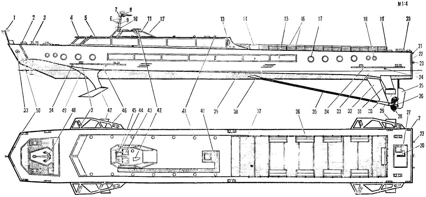

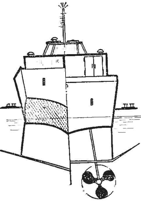
Fig. 1. Model boats hydrofoil:
1 — anchor light (white), 2— bale strap, 3 clamp, 4 — superstructure 5 — window add-in, 6 — top lights “cannot be controlled” (red), 7 — a masthead light (white), 8 — kotikovye signal-flashing light (in the middle red, the edges white), 9 — mast with the pennant, Sea river shipping, 10 — spotlight 11 — the window of the pilothouse, 12 — cabin, 13 — fire extinguisher, 14 — chain, 15 — window of salon, 16 — rail, 17, 18 Windows, 19, 36 — bench, 20 — box switch, 21 — stern light (white), 22 — feed plug, 23 — under eye hook drill for starting motor 24 — screw mount bracket hydrofoil, 25 — wheel, 26 — cone fairing, a 27 — plate switch, 28 — thruster, a 29 — aft hydrofoil, 30 — thrust bearing 31 — stand aft of the wing, a 32 — bracket bearing 33 is a cross-redan, 34 — fence aft of the wing 35 to the propeller shaft 37 — the aft upper deck, 38 — stern tube, 39 — line, 40 — track, 41 — ventilation fungus, a 42 — antenna radar, the 43 — Luke, 44 — side lights (right red, left green), 45 — electrolife, 46 — enclosure of the nasal wing, the 47 — bow hydrofoil, 48 — anchor type Hall, 49 — front nose wing, 50 — nasal plug.
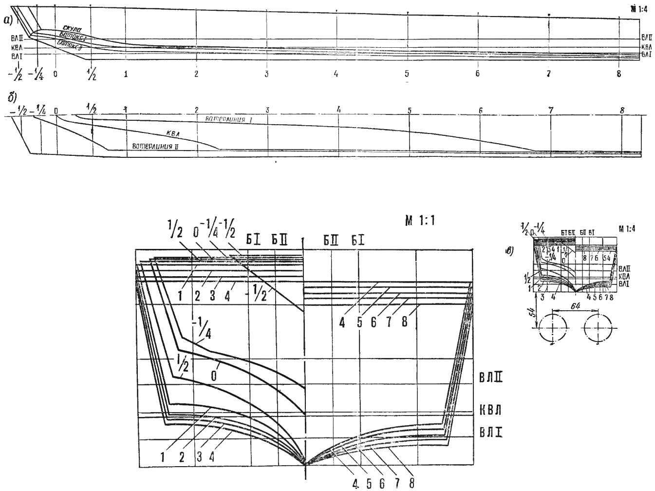
Fig. 2. A theoretical drawing.
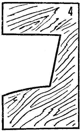
Fig. 3. Template Midel-frame.
Fabricate and install propeller engines and underwater wings. Rotor group (Fig. 5) consists of reducer, lock-breaker, the winding device, two shafts, two mounting brackets, steering and four resinators
Reducer (Fig. 6) manufacture of two gear wheels Ø 40 mm and three gears Ø 8 mm. you Can use other wheels and gears. It is important that the gear ratio was close to 1:5. For the casing of the gearbox you will need three plates of size 120 X 70 mm: two textolite in the thickness 1,5—2 mm, one out of Plexiglas (for the casing) with a thickness of 12 mm, and M3 screws with nuts.
First, using the template of the mid-bulkhead, fabricated from textolite plates of the wall of the housing. Pick up the wheels and gears. Manufacture of “silverfish” 4 mm shafts for the wheels, insert them in the wheel, then drill holes of 0.8—1 mm in the hubs for pin. Attach one wheel by the cotter pin, the second remove from the shaft. In the wall of the reducer drill a hole of Ø 4 mm for the shaft of the left wheel. The hole for the shaft of the right wheel, determine the place, paving between the wheels of a sheet of paper and tightly clasped them. In the same way at the place drill holes Ø 3 mm for shafts of all the gears. Moreover, the toothed gear castle set so that it is in engagement simultaneously with both wheels. Then fold both walls of the gear together, hold in the hand vise and drill out the holes in the other wall. Fabricate from Plexiglas casing of the reducer (Fig. 6A) and then start Assembly. On both sides of the wheels and gears put the puck. The shaft ends of the wheels will release in both directions behind the wall by 8-10 mm, drill them radial holes Ø 1,2—1,5 mm, insert them in the wire, fold in the form of an oval and solder the ends.
The pinion shaft will come out with 7 mm towards the stern for mounting the bushings of the cardan (Fig. 6b). Carved from steel, Art. 3 on a lathe the bushings and secure them with cotter pins on the output shaft ends of the gears.
To display the gear of the lock out of engagement necessary to provide a distance between the front wall of the reducer and wheels to restoranom state gear was part of the clearance and did not touch the toothed wheels (Fig. 6b). The ends of the axis of the gear lock should have a length in the direction of the nose of 25-30 mm, the stern — 8 mm On the long end of the shaft slide the spring guide sleeve and in a slightly compressed state sasplanet. The short end of the shaft serves for fastening the drive clutch.
Gear install in the area of the mid-bulkhead and secure with two reinforced bimson, deck stringers and hard corners (see Fig. 4, 5). Then install the remaining beams, cut holes for the stern tube. Install axial longitudinal bulkheads in the fore and aft parts of the model, made of polystyrene or of plywood with a thickness of 1,5—2 mm. They serve to prevent tangling of resinator.
Key switch (see Fig. 5) consists of toothed gears, springs, two bushings, couplings, drive, and box switch. Clutch drive and check switch are mounted after the installation of the reducer. On the aft end of the actuator push the flag-switch and lock it on both sides zaspirtovanny bushings. The lock actuator attach to the longitudinal bulkhead, the ties are made of soft wire. The aft end of the drive insert into the hole drilled in the transom, the bow connect the clutch with the gear shaft of the castle. Check the operation of the locking device.
A clockwork device is used for convenient and quick tightening of the rubber motor, which is extremely important during the competition. It consists of four stubs, two stern and two bow and hand drill (Fig. 4A). The cover fabricate from two pieces of polystyrene with thickness 2 and 4 mm and “silverfish” to Ø 3 mm. First make the croutons, fit exactly under the hole for the rubber motor, then the bearing plate (glue them with dichloroethane). Fabricate a bracket with the hook.
Adjust the plugs in place so that they constituted a single design with the case was a tight fit and at the same time had holes resinator, do not protrude beyond the dimensions of the model.
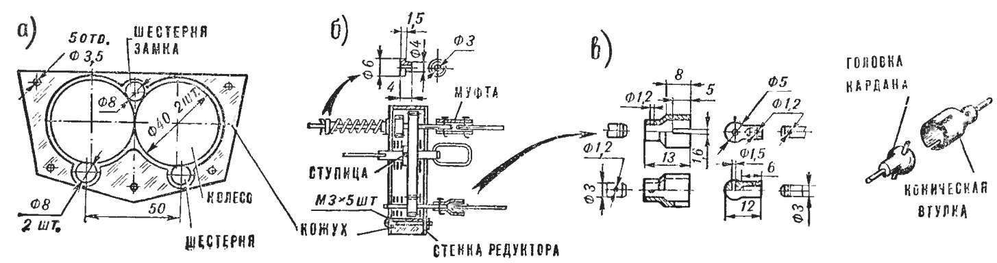
Fig. 4. Installation-rotor and wings:
and — install reinforcement plates and fit the reducer in place; b — installation of deck and bottom stringers, ellerson, reducer; fitting nasal wing in place; the installation of longitudinal bulkheads, drive and box-breaker; — setting of the nasal wing, fabrication and installation winder (bow and stern caps), lining the deck, cutting holes and gluing the coamings g — wing mounts to the body; 1 — window for winding the rubber motor, 2 — reinforcing plate 3 — resistant corners, 4 beams, 5 — reducer, 6 — the hole in the deadwood, 7 — bottom stringer, 8 — deck stringers, 9 — lock actuator switch, 10 — checkbox lock switch 11 — longitudinal bulkhead, 12 — holes for the wing bolts 13 — wing 14 — coaming, 15 — rubber motor, 16 — cracker feed cover plate (20X20 mm), 17 and thrust plate cap, 18 — drill, 19 — an underwater wing, 20 — front wing, 21 — housing, 22 — screw 23 — washer, 24 — nut.
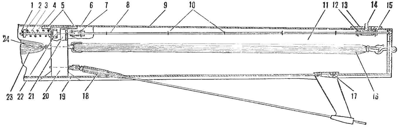
Fig. 5. Propeller group:
1, 7, 12 — pin, 2 — guide bushing 3 — shaft guide lock, 4 — spring lock, 5 — reinforced beams, 6 — coupling, 8 — latch, 9 — deck, 10 — collar, 11 — longitudinal bulkhead, 13 — plate of the switch 14 check key switch, 15 — resistant sleeve, 16 — feed the rubber motor, 17 — screw mount bracket, 18 — restrictive sleeve, the 19th — resistant area, 20 — reducer, 21— gear, 22 — gear lock switch 23 — bow rubber motor, 24 — ring rubber motor.
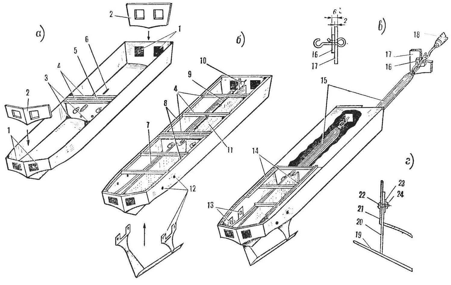
Fig. 6. Gear:
a — kinematic diagram; b — the conditional section; in — Kardan.
Design each drive consists of propeller shaft (see Fig. 1), stern tube, thrust bearing and propeller.
Propeller shaft manufacture from “silverfish” Ø 3 mm and a length of approximately 270 mm (the length of the final install when fitting). On one end of the shaft secure the head gimbal, the second cut the thread М3Х0,5, 15 mm long (Fig. 6b, C).
Deadwood fabricate from brass tube with an inner diameter of 3.5—4 mm and 30 mm long. end with a length of 5-7 mm insert to the Chuck of the lathe, squeeze up to Ø 2,8—2,9 mm and develop a scan hole Ø 3 mm. Then finish with a needle file on a lathe to the required size.
Thrust bearing (Fig. 1) carved on a lathe.
The propeller is manufactured from sheet brass with a thickness of 1,5—2 mm on the pattern. Will watertite on brass round Ø 40 mm and divide the circumference into three equal parts. Using the template of the blade, apply a Scriber (a needle or a sharpened needle files) contours of the propeller blades. Drill in the centre hole Ø 3 mm and cut out billet propeller jigsaw. Clamp it on the screw M3 from the two sides of the cone nuts and bend the blades with pliers 45°, and then solder the nut with the propeller. Give the blades with a sharp end of the hammer profile of an airplane wing, finish with a needle file. Cone cone carved on a lathe and Polish.
The wheel manufacture from the “silverfish” Ø 3 mm brass plates with a thickness of 1,5—2 mm.
The rubber motor is composed of 120 filaments with a length of 800 mm. in the Board Hammer two nails at a specified distance, wrap in neat rows 60 turns of thread. Both ends (near the nails) wrap a string around a coil to a coil in the stretched condition, then at each end make the eye.
Drive Assembly start by installing the brackets 32 (see Fig. 1), and fabricated them from sheet brass with a thickness of 1,5—2 mm. Cut two holes in the bottom of the body. under arms: the distance from transom to aft edge of the bracket is 65 mm, and from side to axis — 30 mm.
Unfold in different directions by 90° of the upper half of the bracket. Insert it into the hole, tight fit “legs” to the bottom of the model and secure with M3 screws with nuts. Solder the thrust bearing. Rotate the model bottom up the speakers and fill the nut with epoxy. The brackets extend so that the distance between the axles was 56 mm.
Next, slip on the propeller shaft of the restrictive bushing 18 (see Fig. 5), stern tube 38 (see Fig. 1) and insert it into the bearing. Then enter the head of the cardan shaft in the tapered sleeve, install the stern tube and glue it with epoxy. Before bonding, check the smoothness of rotation of the shafts and gear. Between the bearing and the hub of the propeller, check the washer, the bolt and lock it to the cone fairing. The propeller is set so that at its rotation force is transmitted to the thrust bearing, not the gearbox. For ease of monitoring between restrictive and stern tubes leave a gap of 1-1,5 mm.
The next important operation — the manufacture and installation of underwater wings. Make these parts from sheet duralumin with a thickness of 3-4 mm. in the manufacture of the uprights of the wings first, prepare a cardboard or celluloid templates. This will watertite stand and wings in full size. Draw on duraluminum their path and saw out with a jigsaw. Give a streamlined shape with a file, sand paper and Polish.
Prepare the casing for mounting the wings: make the sides of the holes for the screws. Install the wings so that the angle between the nose wing and the water surface was 2-3°, and between the aft — 0°. To check the installation angle to the bow and stern wings parallel to the bottom of the hull attach to the edge of the range, between it and the tip of the nose of the wing should be a gap of 1-1,5 mm, and a feed fit snugly over the entire surface.
The model has a superstructure and the wheelhouse. Details manufactured from Plexiglas with a thickness of 1-1,5 mm From strips of black celluloid with a thickness of 0.5 mm and a width of 1-1. 2 mm glue Windows and ribs on the roof of the superstructure. This can be done by applying a solution of acetone and dichloroethane in a 1 : 1 ratio. When gluing push the strip of the superstructure and apply the solution with a brush, the wheelhouse is pressed. For this you need to make a stamp punch and the matrix. For their production you will need a piece of basswood or pine size 100 X 55 X 25 mm, and matrix — sheet of aviation plywood 200X160X3 mm. First, make a punch, then setting its base in the middle of the plywood and pushed a pencil around the perimeter, cut a hole with a jigsaw, so that the gap between the parts of the stamp around the perimeter were 1.5—2 mm. Material for cutting polystyrene, Plexiglas, or celluloid size 200X160 mm Heat the billet above the stove, holding it with pliers, quickly put on the plunger and will push the matrix. Then, without removing the workpiece from the punch, clean the cabin size and stick window.
For deck use aircraft plywood thickness 1,5—2,0 mm. Cover it on both sides two or three layers of Amalita, give to dry out well. Fabricate a stand for the model.
Put the model on the keel-block deck over the stringers and beams all nitrocream, put the deck and set it on top of the load, spreading it evenly over the entire area. In places where the deck adjoins is not very tight, taking her small nails, pre-puncture the holes with an awl.
When the deck is glued, take it hatches to access the gearbox and install resinators. Put the superstructure on the deck, mark its position. Glue to the deck around the perimeter of the inner side rails with a cross section of 4X4 mm cut inside Luke. Cut a hatch in the stern and the size of 300X85 mm (beams leave intact). Aft and close the deck out of plywood the size of 330X90X1 mm. sharpened pencil on a pre-processed fine sandpaper, apply a surface pattern. Cover the Deck with two layers of liquid Amalita. Mount: the nose of the insert under the superstructure, aft against the deck and fix two flags on the inside.
Before painting the model, clear underwater wings. Zashpaklyuyte hull and deck so that the surface was smooth and even, and matte. Repel the waterline — glue with acetone black celluloid, mark and glue the window of the cabin and other details. Paint the Board with the spray above the waterline in ivory (it is necessary to apply 2-3 coats). Flip the model bottom up, using the masking tape and paper close at the waterline on the sides and paint the bottom with red paint. Let dry 15-20 min, remove the tape and after 1.5—2 hours, scrape the paint with a sharp scalpel from the waterline, the Windows of the salon, etc. Then glue the portholes. Deck — light brown. Lifelines are made of wire Ø 0.2—0.3 mm solder neatly to the posts, paint with a brush in white. Under the rack to pre-drill the holes.
Prepare and install the fine details of alarm systems, fire fighting, rescue equipment, etc.
Check the smoothness of rotation of the drive — in, manually turn the propeller gearbox.
Convinced of the reliability of the key switch, place it in the position “locked”. Get model — it is more convenient to do it together: one holds the model for case (turning her nose to his), elbow pressed to his side. The second Modeler by inserting the hook into the eyelet to the winding device, retreats half a step and stretching the rubber motor by 1/3 of its length, gets it to 15-20 turns. The sequence of winding the following: bow, stern, bow.
Carefully lower the boat into the water, expand at the rate, rotate the check box of the switch and release model. If she’s not out on the wings, increase the angle of attack, if the nose is “jumping” on the water, reduce. Adjust the rate, gradually increasing the number of turns of the rubber motor.
The maximum cruising range of models 50-60 m.
Recommend to read
 COMPACT SPRING
Compact is only the spring tension. And is designed for compression always takes a lot of space when storing. However, it is easy to make compact, if the pre-squeeze in the vise so that... SARATOV “THE LANCERS”
Has become a matter of habit the appearance of the next articles on the subject of electric mobility. No wonder: in the USA the production of electric vehicles is 1/5 part of the...
