 I must say that homoplastic aviation material will not name. However, tests of models made with this lightweight and durable material, showed that he is quite suitable for various models.
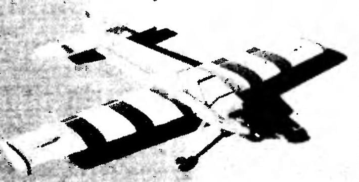
After the construction and testing of a simple training model from this material, called “Homoplastic-1”, I wanted to make a more perfect machine. I tried to fulfill at least three conditions. First — flight characteristics of the model should be significantly better than that of devices of the standard assumptions of ARF. The second time, the Assembly should be approximately the same. And, third, to ensure ease of construction and simplicity of operation.
Before you start making models of homoplastic, it makes sense to find information binder compositions for bonding. In the Assembly of the previous model (“Homoplastic-1”) had adhesive joints of large area, used glues “rapid” or “Moment”. The high-quality surface preparation, the application of these binders are valid and in the Assembly “Homoplastic-2”. However, if possible, it is better to use specialized adhesives: brand “Contact cement” made in the USA or domestic “BF-2 for metal.”
The fuselage (option 1). Elevated vibratory loads was forced to change the mounting force of the cartridge on the “Homoplastic-2”. From this “stuff” depends on the reliability of the plant and, consequently, the quality of the flight model. Power frame No. 1 and panel cartridge sawed out of plywood with a thickness of 10 mm. Openings and window relief cut in place, in accordance with the size of the motor. The Assembly was carried out using the epoxy resin, the reliability of the fixed screw. The second power frame and panel chassis sawed out of plywood with a thickness of 10 mm. After cutting out all the holes parts are mutually adjusted and glued with epoxy. If there is any doubt as thick construction plywood, it is best to replace it peraclean plates from aviation plywood with a thickness of 1-2 mm.
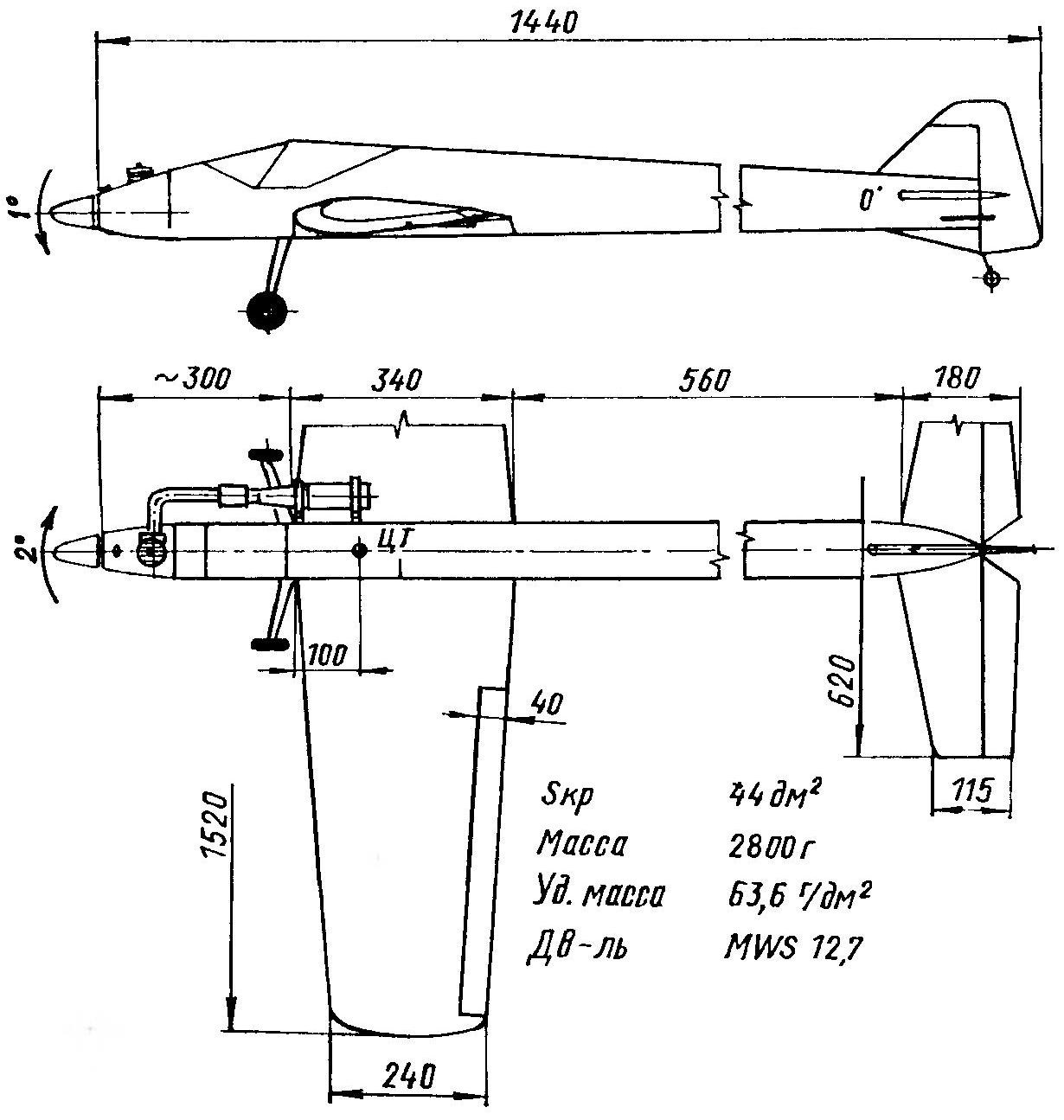
The geometric training of the pilot model type “of Homoplastic-2”
The rest of the cross set of the fuselage — balsa medium density 5 mm thick, reinforced with thin fiberglass. Power pads were cut with a box cutter and cut with a jigsaw. When installing the lining, special attention is paid to the quality of the adhesive joint in the bow. The fact that the fuel and exhaust products destroy the structure of glue “Moment”, and any narola or crack cause accelerated stratification. Adhesives “Contact” and “BF-2 for metal” is less sensitive, but also not eternal. To make joints more reliable, they are mandatory prior to application of glue should be treated with fine sandpaper to a matte state and degreased with acetone.
The fuselage (option 2). The power cartridge provides undeniable advantages in the replacement of the engine and the entire fuel system, moreover, it simplifies the repair. However, many modelers there is no need of frequent change-rotor. This case was developed by the “classic” scheme. Besides the simplicity, it provides the best vibration isolation of the fuel tank.
First the bulkheads are cut from quality plywood with thickness of 10 mm, after which it was powerleveling holes for the screws of the motor and under the thrust of “gas”. Window relief cut in place, in accordance with the size and position of these items.
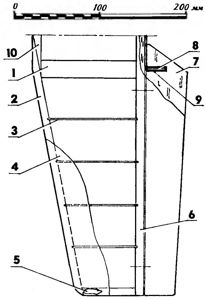
Stabilizer:
1 — root rib (balsa s 10); 2 — the leading edge (balsa s 10); 3 — rib (balsa s2); 4 — skin (balsa s1,5); 5 —ending (balsa s 10); 6— trailing edge (balsa s 10); 7 — Elevator (balsa s 12); 8 — clip (wire Ø2 OBC); 9 — bushing (duralumin, tube 3×0,5); 10— plate(balsa s 10)
The second frame was also made from quality plywood, but the thickness of 6 mm. Should be aware that through the hole in the second bulkhead is installed in place of the fuel tank — this should be considered when determining the size and layout of the window.
The remaining elements of the transversal set of the fuselage are cut from balsa medium density 5 mm thick, reinforced with a thin fiberglass Stringers were made of Linden slats.
When assembling, first mount the inner frame of the bow, consisting of the first three frames, stringers and plywood side panels, installed in the dock area of the fuselage with the wing. The Assembly was carried out on a flat surface, with continuous monitoring of frames perpendicular to the reference plane. Because the site is experiencing heavy loads, for bonding used epoxy resin.
The next stage of Assembly / installation homoplastic plating. First tested the accuracy of the stitching: if necessary they were fitted to each other. Further, the frame is docked with the Board sheathing, and then consistently recorded top, bottom and other side of the fuselage. The hood is fabricated on a foam dummy, which after polymerization of the resin was removed with acetone.
For option 1 with a cartridge instead of a hood is recommended by simply extending the side panels and lining.
The wing is suitable for both variants of the fuselage. In his design used a separate drive ailerons that for an Amateur model (even with the flight bias) is a rarity. The fact that the model is perfectly symmetrical, almost impossible, so when performing certain maneuvers asymmetry felt in control. The introduction of a kind of differential in the Aileron easily corrects this deficiency.
When installing the servos are the size of “micro” you need to shoot them with a vibration-isolating bushing, for “MIDI” and “standard” you can leave them.
Beam flange cut from balsa with a density of 0.15—0.2 g/cm2 or from quality Linden slats 8×5 mm. cross-section of the Wall of the Central part of shaped balsa average of paid and plywood 1 mm. In this operation, use thick cyanoacrylate glue or liquid epoxy resin. Cross set is made of balsa, covered with fiberglass with a thickness of 0.03 mm using a parquet varnish.
Remark. Easier and faster to paste the first sheet of veneer, and then by the patterns cut out of it the right parts.
Wing profile modified NACA. In the manufacture of the wing was tested and a more sophisticated “blunt” profiles (bending the cardboard to a large radius it is more convenient).
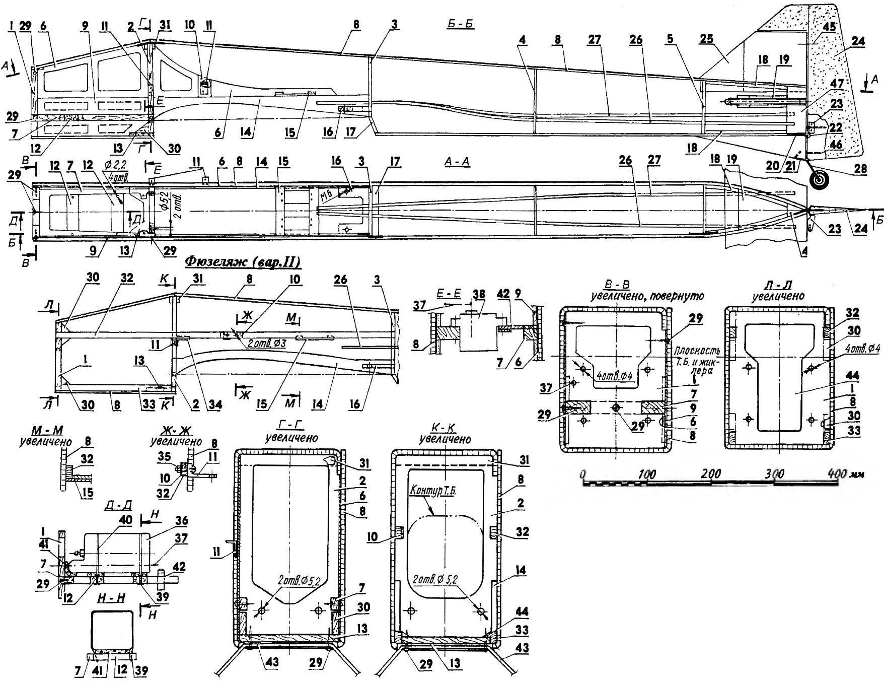
The fuselage of the training aircraft (on the types of side in terms of cartridge and steering apparatus conventionally not shown):
1 —frame No. 1 (plywood s10); 2— frame №2 (plywood s10); 3 — frame № 3 (s5 balsa + fiberglass s0,03); 4 — frame № 4 (B5 balsa + fiberglass s0,03); 5 — frame № 5 (s5 balsa + fiberglass s0,03); 6 — power panel (plywood s1); 7 — bar cartridge (plywood 10); 8 —fuselage skin (cellular polypropylene s4); 9— additional pad (dense balsa s3): 10 — optional trim (plywood s1); 11 — bracket resonance tube (made of anodized aluminum, sheet s2); 12— insert (balsa s10); 13— panel chassis (plywood s6); 14 — wing cradle (two layers of plywood s1); 15 — bar servos (2+2 layers of plywood s1); 16— bar wing mounting (plywood s6); 17 — the lower part of frame No. 3; 18— strengthening of the joint covering (balsa s5); 19— plate stabilizer (balsa s5); 20 — panel mount tail stand (made of anodized aluminum, sheet s2): 21 — clip (OVS wire Ø1,5); 22— thrust washer; 23 — pylon (plastic); 24— the rudder (lightweight balsa s10 + fiberglass s0,03); 25 Kil (light balsa $10 + fiberglass s0,03); 26 — drive rudder (Bowden 3507 company “Graupner”); 27— Elevator drive (Bowden 3507 company “Graupner”); 28 tail strut (wire OVS Ø2) with wheel Ø30 firms Termik: 29 — tapping screws; 30 — scarves (four layers of plywood s1); 31 — lining the frame # 2 (balsa s5); 32— upper stringer (Linden or pine, the rack 10×5); 33— lower stringer (Linden or pine, the rack 10×5); 34 panel steering servos throttle of the carburetor (2+2 layers of plywood s1); 35 — screw and M3 nut; 36 — fuel tank capacity 350 ml; 37 — axis thrust throttle of the carburetor (Bowden 3507 company “Graupner”); 38 — servo throttle of the carburetor (HS-81MG); 39 — pin (wire Ø1 OBC); 40 — clip (plastic or rubber); 41 — vibration isolation (foam rubber); 42 panel servos (2+2 layers of plywood s1); 43 main landing gear (aluminum. sheet s3); 44— window ease; 45— axis loop of the company “Thermals”; 46— joint (wire Ø1,5); 47— caudal boss
The wing of the airplane:
1 — rib No. 4 (balsa s8); 2 — casing (polypropylene s2…2,5); 3 — rib No. 3 (s5 balsa + fiberglass s0,03); 4 — the wall of the spar (balsa s2): 5 — shelf of the spar (thick balsa; section AC from 15×5 to 8×5); 6 — tie bar machines (2+2 layers of plywood s1); 7— rib # 2 (s5 balsa + fiberglass s0,03); 8— toe rib (balsa 55 + fiberglass s0,03); 9— rib No. 1 (s5 balsa + fiberglass s0,03); 10 —head (thick balsa s10); 11 — front panel (plywood s1); 12 — pin wing mounting (Ø5 beech); 13 — termination of center (two layers of balsa s6); 14— hog (plastic); 15— rear flange (thick balsa 15×12); 16 — Aileron (light balsa s12); 17 — the ending (Vileika balsa); 18,20— axis hinge company “Thermals”; 19 — rod Aileron (wire Ø2); 21 — rear panel (plywood s1); 22 — power insert wing mounting (plywood s1); 23 — reinforcement of the joint edges (thick balsa s5); 24 — reinforcement of the seam covering (cellular polypropylene s2); 25— lateral wall (balsa s5); 26 — bottom panel (balsa s3); 27 — the spar web (thick balsa s5); 28 force the wall of the side member (plywood s1); 29 — the adjusting plug
It should be noted that there are several types of homoplastic — it makes sense to buy more slim.
The adhesion of the plating begins with the lower part of the wing, and after polymerization of the adhesive was attached to the top. Additional pads were placed on the glue “Moment”.
The best material for the manufacture of flaps — lightweight balsa. The insert viskazalas s-cone to cut grooves for the hinges. To increase the rigidity and reduce the impact of fuel items papered fiberglass thickness of 0.03 mm two-component parquet lacquer.
The tail Assembly. It should be noted that there is no need to do composite stabilizer, it is quite suitable carved from balsa and light ply plate with a thickness of 10-12 mm and covered with fiberglass. To offer readers models of any area of the stabilizer was used from another model.
The trailing edge of the stabilizer is made of balsa average density of a cross section of 10×10 mm at the root and 10×6 mm at the end. Before assembling the stabilizer was cut the holes for the hinges of the rudders. The front edge is cut from balsa with a density of at least 0.15 g/cm2 with a variable cross section from 10×6 to 10×10 mm. In propilivanie edges have grooves for the ribs and the grooves for the hinges.
Ribs carved from balsa wood with a thickness of 2 mm. Cladding made of the same material thickness of 1.5 mm. frame Assembly was carried out on the liquid, and the cladding is a thick cyanoacrylate glue. After drying, the stabilizer is profiled and covered with a single layer of liquid nitroblue type of AGO with the subsequent polishing. Before installation to the place he is papered with a thin film (or puttied and primed with paint resistant to methanol). The elevators are made of balsa and light ply, 12 mm thick, after profiling laminated glass with a thickness of 0.03 mm on a parquet varnish. When installing the stabilizer, the area inside the fuselage with balsa glued 3 mm thick. This additional lining locks the stabilizer from shifting.
The keel and rudder carved from balsa and light ply with a thickness of 10 mm. After the treatment with a knife and sandpaper they are tight fitting fiberglass thickness of 0.03 mm on a parquet varnish. When mounting the keel inserted into the groove of the frame and the rear lugs of the fuselage at a depth of 6-10 mm.
Chassis. Landing gear is made of hardened sheet of aluminum, thickness: 3 mm Wheels — firms Robby, or any other similar tires of rubber — they are much easier than usual. In the operation of models at sites with poor coverage or as a flying stand to debug VMG recommended further strengthening of the rack with a thin cable. One end clings to the engine frame, and the other — for wheel axle (or nearby).
Rotor group. The model was operated with engine MVVS volume is 12.7 cm3 with a resonant pipe, for which the fuselage is provided with the special attachment points. Prop Master SKIMITAR 330×150 mm. in diameter On the model installed and other engines with working volume from 6.5 to 15 cm3. Fuel tank company Tiger Tangier with a capacity of 420 cm3. For the second option, you can use the tank O. K. Model with a capacity of 370 cm3. The tank is isolated from the base cushions are foam with a thickness of about 10 mm. by Changing their thickness, we can slightly change the height of the tank relative to the nozzle.
Finish. All wooden parts of the model covered with two layers of two-component parquet lacquer. The seam of the fuselage and trailing edge of the wing are covered with self-adhesive film such as “ORACAL”.
The tail should be painted with synthetic enamel or paste over the same film.
D. CHERNOV
Recommend to read
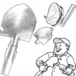 AND SAW, AND “OPENER”
Some time ago folding blades supplied by industry mainly for the army. Now widely available and are popular with motorists and hunters, geologists and fishermen, campers and even...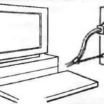 THE COMPUTER ON THE CIRCUIT
As you know, power outages often lead to loss of information entered in the RAM of the personal computer. And nine times out of ten this trouble occurs in case of accidental pulling of...
