 Simple radio-controlled model aircraft. Do note that this article is designed for those who prefer to build RC models are not alone, and together with two or three associates. For such a complex and expensive Hobbies well together and the work is fun and the purchase of remote control equipment and engine “rainbow 7” is significantly cheaper. By the way, for beginners you can recommend not too expensive equipment, FOCUS 4, FOCUS 6 Korean company Hitek — the first cost is about $185, the second $220.
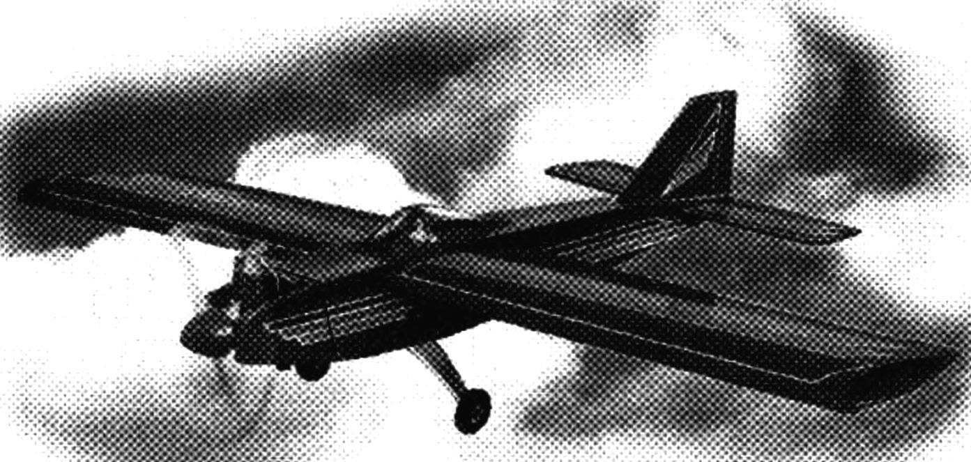
We bring to attention of readers of radio-controlled model of “Maple-7” — it is simple, has high strength and has good flight performance.
Manufacturer model it is most convenient to start with the Assembly of the vertical and horizontal tail. Any design features of these sites do not have. The keel and rudder carved from balsa plate with a thickness of 5 mm, but the horizontal tail is made from balsa strips with a thickness of 8 mm, followed by the tight wrap of the “Supersonichot” or Patriotic Mylar film. Elevators (and rudder) are mounted on hinges such as “thermals”.
To collect the best fuselage upside down on a special bench, consisting of a base — a flat Board with a thickness of about 30 mm and lodgement wedge-shaped. When installed on the berth billet construction the horizontal fuselage, passing through the axis of the engine and the plane of the chords of the wing should be parallel to the base of the bench.
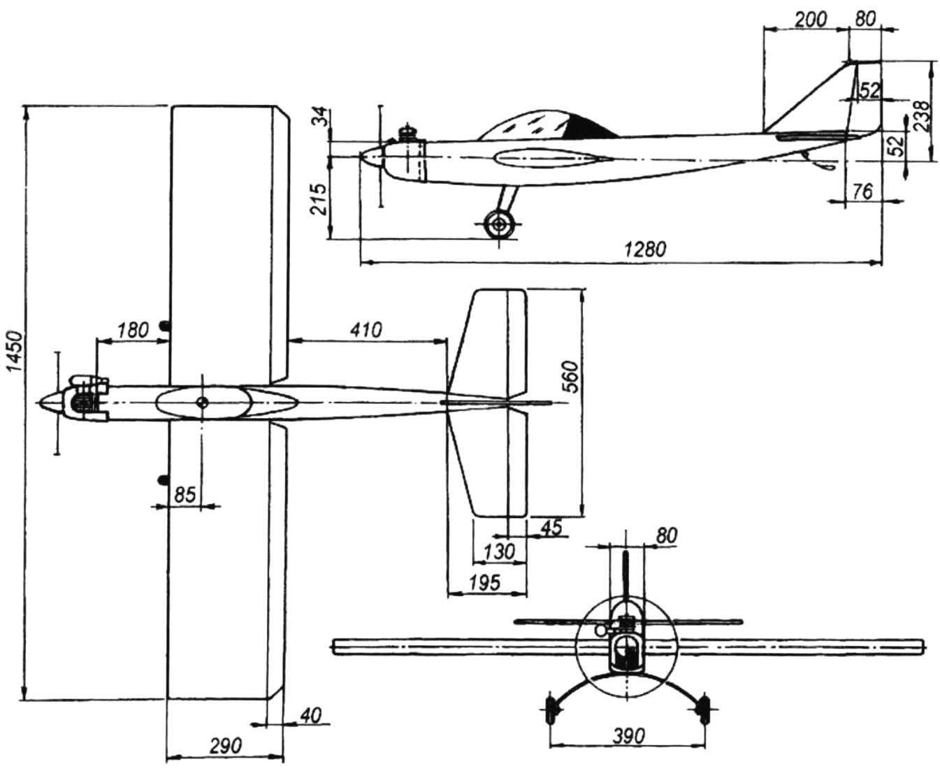
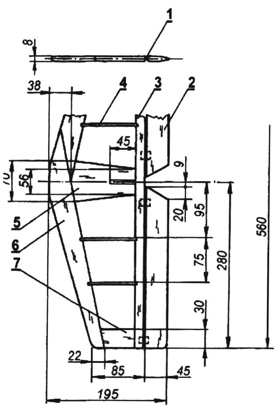
The geometric scheme of the RC model the “Maple 7”
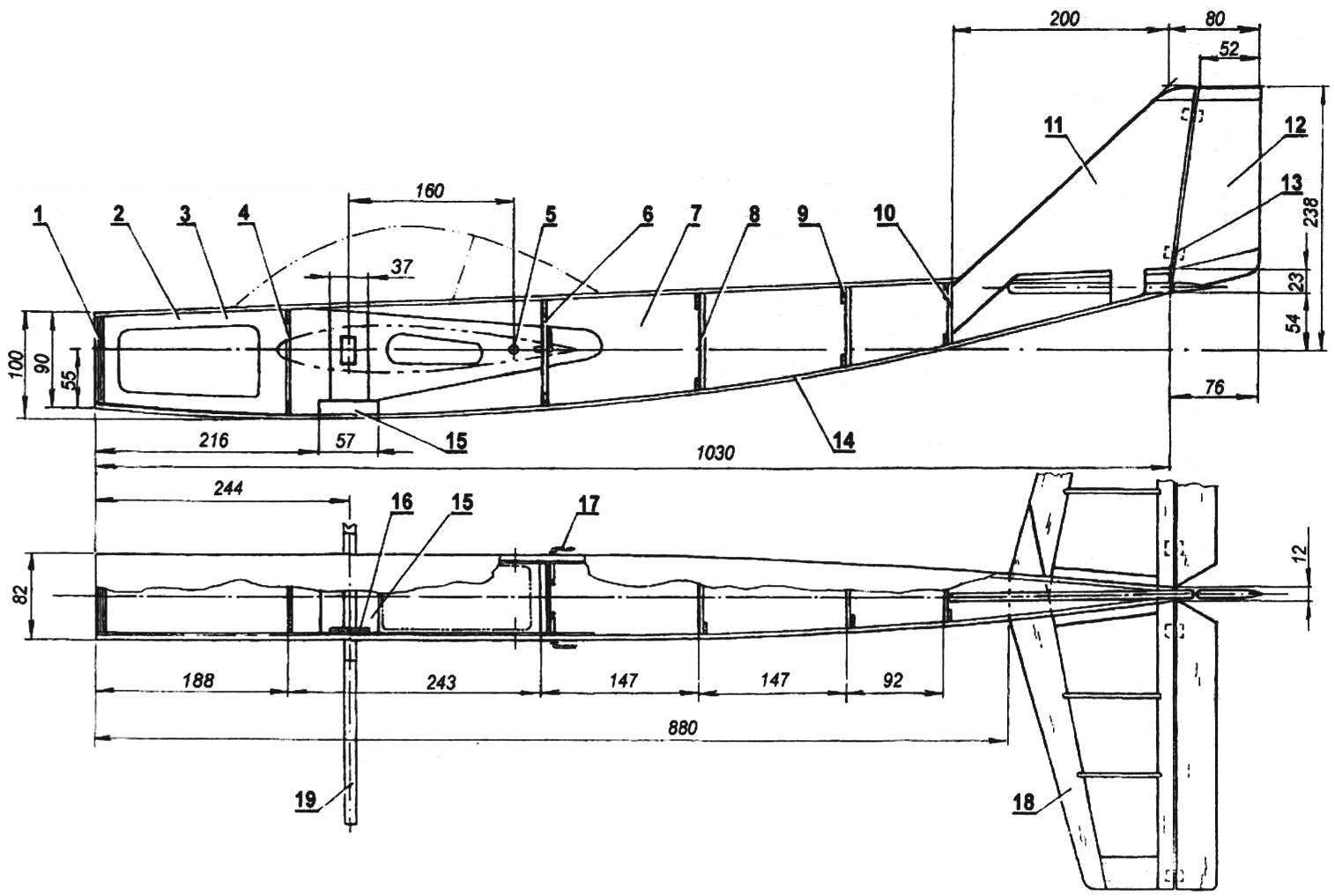
The layout of fuselage for RC models “Maple-7”:
1 — frame 1 (switching from two plywood plates s3 and two plates s1); 2 — the top panel of the fuselage (balsa, plate s2); 3 — strengthening side panels (plywood s1); 4 — frame 2 (plywood s3); 5 — the location of the holes for the rear pin fixing console; 6 — frame 3 (plywood s3); 7 — side panel (balsa s4); 8 — frame 4 (frame balsa blanks s3); 9 — frame 5 (the frame is balsa blanks s3); 10 — frame 6 (frame balsa blanks s3); 11 — the keel (balsa plate s5); 12 — the rudder (balsa plate s5); 13 — loop type Termik; 14 — lower panel of the fuselage (balsa, plate s2); 15 — bearing chassis (plywood s10); 16 — strengthening of Board (plywood s4); 17 — the lever of a drive of the Aileron; 18 — horizontal tail; 19 — installation of the wing joiner
For the manufacture of parts is recommended to use Plaza — accurate drawing of the fuselage in full size. In accordance with this Plaza balsa 2 mm thick plates and cut the upper skin of the fuselage, after which the billet is placed in a closed plastic wrap and staple it with pins fixed frames. Note that the front frames are machined from aircraft birch plywood, and three tail, which is a rectangular frame assembled from balsa strips 3 mm thick.
Practice has shown that the engine is convenient to mount on the model for its back wall. After determining the locations of the mounting bolts of the motor in the windshield frame, glued two pieces of plywood of 3 mm thickness, cut out the window of relief, and then the frame on both sides glued with millimeter plywood.
The top panel of the fuselage carved from balsa veneer with a thickness of 2 mm, a longitudinal direction of the fibers, the lower transverse. In its front part (between the first and second frame) the top panel is thickened to 4 mm. the side of the fuselage is cut from 4 mm balsa veneer and reinforced in the fore part thereof with plates of 1 mm plywood.
Wing “Maple” has a symmetric biconvex profile Yak-55 with a relative thickness of 12%. Wing design is extremely simplified and lightweight. Cross set each wing consists of four ribs of balsa 4 mm thick; the root rib is glued from 4 mm balsa and the 4-mm plywood, end — 6 mm balsa. Shelf wing spars from pine slats with a cross-section 6×4 mm, wall — balsa 3 mm thick Front edge pine, Reiki 6×6 mm, rear — balsa, 20×4 mm.
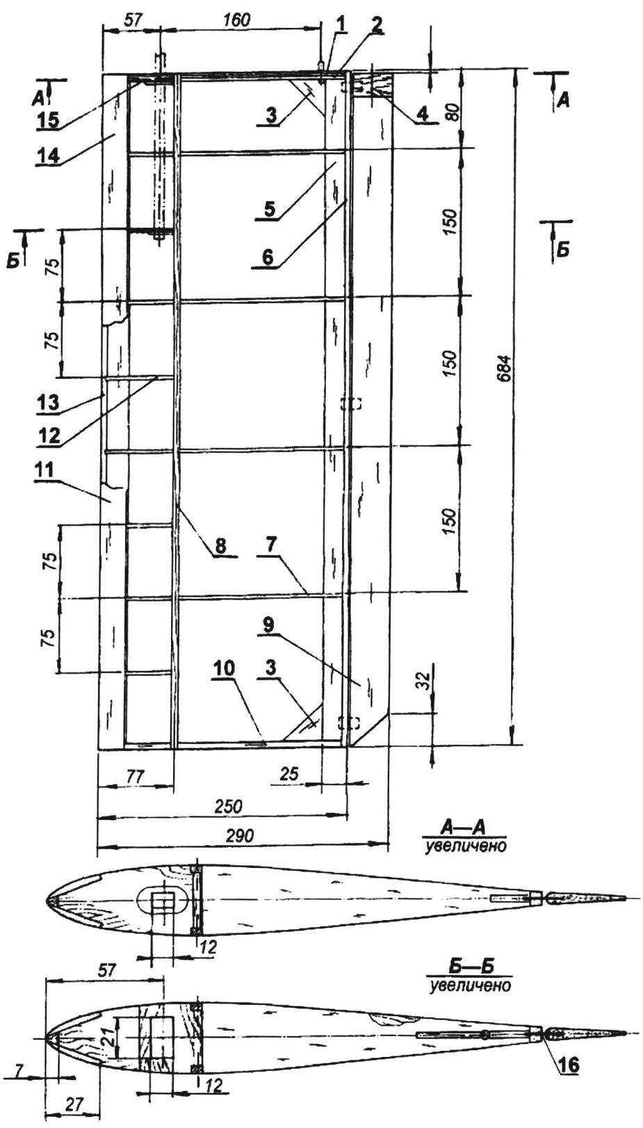
Wing:
1 — root rib (balsa s4); 2 — strengthening of the root ribs (plywood s4); 3 — solitaire (balsa s3); 4— strengthening the root of the Aileron (plywood s1); 5 — trailing edge (balsa rail 4×20); 6 — trim the trailing edge (balsa, “1 rake 6×9); 7 — rib (balsa plate s4); 8 — shelf side member (pine, battens 4×6); 9 — Aileron (balsa plate s6); 10 — end rib (balsa plate s6); 11 panel front edge (balsa plate s4); 12 — polonaruwa sock wing (balsa plate s4); 13 — front edge (pine, rail 6×6); 14 — location of the locating pins of the wing; 15 — strengthening the area of the opening under the setup pin (plywood s3); 16 — loop type Termik; 17 — rear mounting pin (beech, Ø4)
Horizontal tail:
1 — loop like “thermals”; 2 — the Elevator (balsa plate s8); 3 — trailing edge (balsa rail 8×15); 4 — rib (balsa plate s3); 5 — the Central part (balsa plate s8); 6 — the leading edge (balsa plate s8); 7 — ending of the stabilizer (balsa s8)
Before assembling the wing prepared a set of ribs, then going to a frame consisting of ribs, pine shelves of the spar, a trailing edge, the front edge of the pine and balsa panels leading edge. The final operations are assembling the balsa walls of the spar and bonding kerchiefs gain. For assembling the frame, it is desirable to use the slipway of a flat Board, which is fixed to the rail — lining under the back edge of the console. Its thickness should be such that the plane of the chord of the wing was parallel to the plane of the bench.
Ailerons — balsa, profile has the form of a trapezoid, the thickness of the trailing edge is about 3 mm. In the root end of the slotted groove under the lever Aileron; the very same root part is strengthened with plates of 1 mm plywood. Mount the Aileron to the console — on three loops such as “thermals”.
Mount the wing panels to the fuselage — on a pine pin glued in the fuselage. Fixing consoles on the pin is carried out with self-drilling screws, passed through the root rib and entering the pin to a depth of about 5 mm.
Stand the main chassis “Maple” made of sheet of aluminum of a thickness of 3 mm. Width of the strut from the fuselage is 40 mm, the axis of the wheel 16 mm. strut to the fuselage with four bolts M3, glued to a support chassis, and nuts M3. Wheels with a diameter of about 70 mm and a width of about 15 mm the easiest way to choose from children’s toys. It is advisable to only equip them with a plastic or dural sleeve.
The engine hood wikiepedia of fiberglass and epoxy on the foam disc. You can also beat the hood out of sheet aluminum brand AMG. The use of Plexiglas or polystyrene undesirable heating of the engine is large enough, and this can lead to deformation of the part.
The canopy is cut from a plastic bottle of suitable shape and preferably blue or green. You just pick on thin-walled vessel suitable for the shape of the surface.
To fit the console and parts of the tail best film of the “Supersonichot” or Mylar film technology, well known to the modelers, using glue BF-2 and iron. All outer surfaces of the wooden parts covered with parquet lacquer or enamel.
Before first flight you must check the alignment of the model. For this curb model is mounted on a stand, which is a base with two triangular supports, while the vertices of the triangles are located in the area of the root ribs. The center of gravity of the model need to be in the area about 30 percent of the mean aerodynamic chord (SAH).
To verify this, you need to measure the distance from the front edge of the wing to the pivot point, in which the model will be in an indifferent equilibrium, divide this distance by the length of the chord (straight wing) and multiply by 100 percent. Note that the front alignment will not raise the nose of the model when landing and the rear will make the model unstable.
If you have never raised RC plane in the air, it is best to first skills to the simplest of exercise equipment, by means of the built model. You only need to hang the model from a string so that it was in the horizontal plane. With a good wind, by manipulating the rudders height as well as the ailerons, you can quickly learn to fend off roll, enter the unit in the “dive” or “pitch up”, rotate it around the vertical axis. This technique, by the way, is not new — it started way in the sky is a glider pilots in flying clubs: they set the glider on a single wheel nose against the wind and held it in the “horizon” with the control stick and pedals.
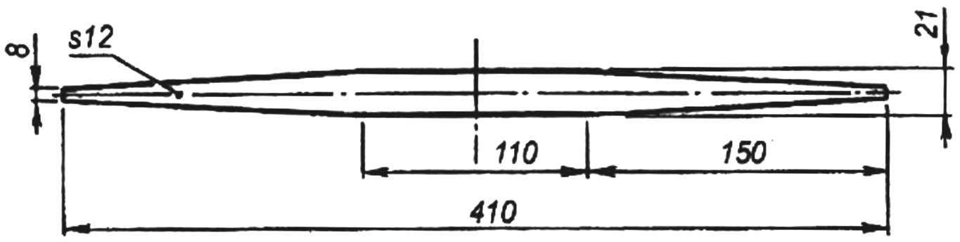
Installation of the wing joiner (pine)
Well, now — flying! Note that the engine needs to work steadily in horizontal position model and raised the nose of the model to an angle of 35 degrees. Orient the model with the nose against the wind and hold the check engine response. Then install a small gas release model and begin to gradually increase the “gas” to the maximum. During the run the model is typically deployed to the left due to the reaction of the propeller, so you need to have time to fend off a reversal with the variation of the rudder.
When the model’s speed approaches the speed of separation, the Elevator smoothly it is necessary to reject “the”, and the model will be in the air. Note that the climb should be under a slight angle. Be ready to parry rolls caused by turbulence and eddies near the earth’s surface.
Table coordinates of the airfoil Yak-55—12%

After reaching a height of about 50 m, try to do four turn 90 degrees with subsequent planting. When you rotate the model, use the control to enter the ailerons in roll (about 45 degrees) and reject the Elevator “on yourself” — when this model enters the turn. After the turn, move the Elevator to neutral position and remove the model from the roll.
After the fourth turn model, just like at takeoff, is to fly against the wind. For planting it is necessary to dump “gas” and to translate the model into planning.
When the model drops to a height of one meter, it is transferred to the horizontal flight. The airspeed will gradually decrease to the landing, and the angle of attack of the model increase, and as a result it will begin to parachutiste. Properly designed Seating mode provides the touch the land all three wheels of the chassis at the beginning of parachuting.
I. SILVER
Recommend to read
 THE ELECTRIC GUITAR IS OUT OF THE ORDINARY
Talking about various musical instruments, it is impossible not to recall the, perhaps, popular and indispensable in modern orchestras and rock bands. Of course, this is the electric... PAINT WITHOUT SECRETS
Assortment of paints (coatings) are currently quite wide, and therefore, in such a variety without the advice quite difficult to understand. Get expert advice from the seller not always...
