It also proposed a tapered fuselage-monocoque laminated of fiberglass and epoxy resin. For vyklicky need conical wooden disc, carved in accordance with the internal dimensions of the shell. It should be noted that the length of the bar shall exceed the length of the fuselage beams of 15— 20 mm at both the front and rear. The finished blank is carefully bandaged with a strip cut from a plastic film and glued two or three layers of fiberglass so that the total thickness of veclachi did not exceed 0.5 mm. Further, Vileika is wrapped with polyethylene film and bandaged tightly with a rubber band. And finally, the remaining “tails” attached durable fiberglass twine, and the disc is suspended by the upper “tail” of the hood, while its lower “tail” binds cargo, such as weight weighing 24-32 kg or even a bag of sand.
The next day the shell is separated from the blanks, and it is glued molded out of fiberglass or paper and epoxy resin are cylindrical insert designed to mate with the fuselage front fairing. In the rear part of the beam is glued in the balsa plug. Front fairing wikiepedia exactly the same as the beam or the nacelle.
The fuselage elektroleta:
1 —front fairing (Vileika of fiberglass and epoxy resin); 2 — insert (Vileika of paper or fiberglass); 3 — beam (Vileika fiberglass); 4 plug (balsa).
Keel elektroleta:
1 – rib (balsa s1,5); 2 – the front edge (balsa rack 5×5); 3 – M2 nut; 4 – the root rib (balsa rack 6×5); 5 – flange rear (balsa rail 6×3).
Fuselage beam and the technological process of veclachi:
A — rod; B — bandaging rod plastic tape; taping fiberglass rod and wrap with plastic wrap vyklicky; G — bandaging vyklicky rubber band; D — curing resin under the hood.
The nose part of the model with battery case:
1,6,8 plate pin (brass band 6×0,5); 2 springs (wire OVS d0.5): 3 – fuselage fairing, front: 4 – batteries or rechargeable batteries; 5 — fuselage; 7 pencil box (Vileika of epoxy resin and fiberglass).
The BATTERY CANISTER is a fiberglass cylinder with an inner diameter of 16 mm; the middle cylinder is fixed to the Central contact of the brass strips with a cross-section 6×0,5 mm, the same strips are fixed two pairs of batteries inserted in the cylinder. For more reliable contact under the spring strips are introduced from provoloki type of OVS with a diameter of 0.5 mm. Connecting elements is series-parallel, which connected in parallel two pairs of series-connected batteries. In the Central part of the wing (on the lining) must be set microtubles or homemade mini-switch.
The PROPELLERS have a diameter of 150 mm at a step of 150 mm. to Make them better all of the lime on the type of those installed in high-speed cord models.
The wing and stabilizer on the fuselage are attached with rubber bands.
To do this, in the area of the stabilizer and wing to the beam glued the balsa insert, forming a connecting platform. However, with the gluing of the front docking area should wait, choose the first experimentally uncoupled model.
This operation is performed when the trial runs on schedule while the power is off. Moving the wing along the fuselage beams, changing the angle of its installation, and the installation angle of the stabilizer, you should make sure the flight model. You can then glue the connecting pad under the wing so that the position and installation angle of the wing fit obtained experimentally.
Adjustment of the electric motor in flight is to trim the blades of the propellers with model tests after each pruning in motor mode. After reaching the optimum thrust of the blade it is desirable to balance, Polish and coating parquet varnish.
Launches should be taken into account that the duration of the flight motor when using rechargeable batteries or Alkaline batteries can be quite large, so care should be taken to install a simple timer, for example, wick-type, disconnect the power to the engines.
I. NISTRATOV
Recommend to read
 CONVENIENT AND ON THE CEILING
Observance of measures of fire safety is necessary for everyone, always and everywhere: at work, at home. And if the companies behind this control is performed by fire supervision...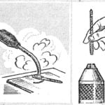 WHEN A DRILL OF SMALL DIAMETER
In the "M-K" № 9, 1985 our reader Yuri Zhdanov recommended for clamping in the Chuck of a drill of small diameter to apply the "shirt" is a spiral of thin wire. However, a hand drill and...

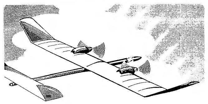 Electrics have had a steady popularity among modelers, but she sometimes wears some kind of theoretical. It seems that many believe the making of “trains” is inconceivable without supernatural and superaccumulation. Meanwhile, a relatively simple Svobodnaya electrics with the most common DC motors-5-19 and is powered by standard AA batteries or rechargeable batteries can be done in any model circle or even at home.