Immediately it should be noted that the construction of such a model is designed for young athletes, has acquired nekotrye the experience of creating miniature aircraft. It is advisable that you know how not only with sufficient accuracy to treat the wood, but knew the intricacies of using epoxy adhesives. One of the very important requirements — experience with Mylar films. The fact that this priceless obtienes material will not only save a considerable portion of the mass of the model, but will dramatically reduce the time of its production due to virtually complete elimination of the traditional operations of puttying and sanding of exterior surfaces. Once again I repeat — this will be achieved only with proper handling of Mylar film! You may need to practice. This time will pay off handsomely. And polyopia the MiG-25 he will not only give an amazing combination of strength and lightness of the finished design, but may even allow you to avoid most of the painting operations in the selection of a desired shade metalized lavsan.
Fig. 1. Principle drawing of the species in plaie design polyopia jet self-summer-prototype:
A — the original drawing of the aircraft (performed with maximum precision or used by a tracing with reduced photocopies; overall size is small is desirable for a better perception of the holistic nature of the shape of the aircraft), B — variant polyopia with flat fuselage while maintaining large position of end sections of the wing and stabilizer, In — interim version (used later as main), G — the option of preserving the scale of proportions cantilever sections of the wing and stabilizer, D — final version (used to determine the basic proportions of the models and choice of scale).
Polk — maksimalnaya the height of the underwing fuselage in the area of the main landing gear,
M FR.— the scale of the created nopie regarding this aircraft (reference nigritia value).
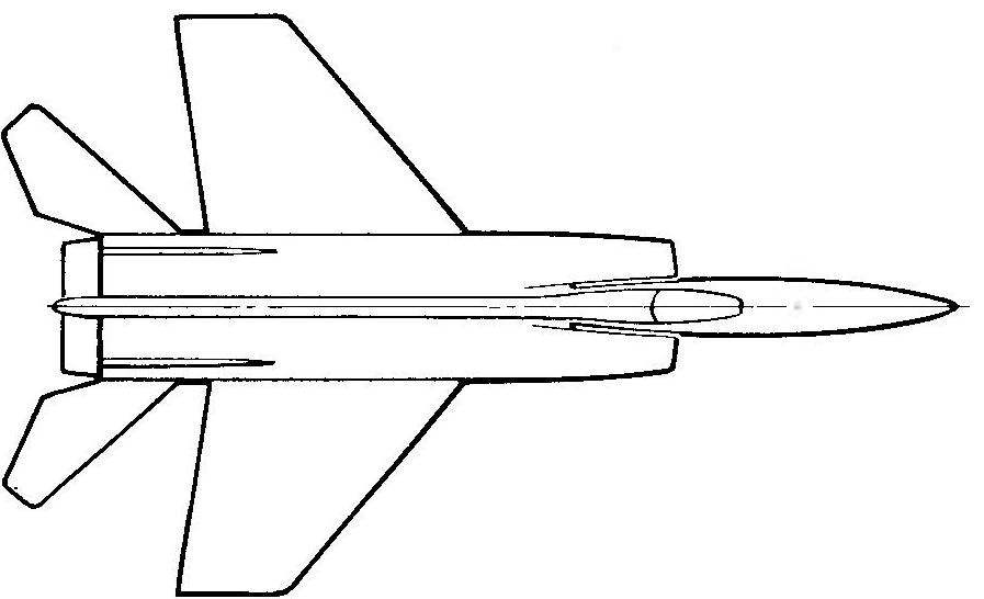
The MIG-25 Heavy fighter jet.
Fig. 2. The Central part of the fuselage:
1 — trim the gain (plywood 2.5 mm), 2 — cheek side of the sheathing (plywood 1.5 mm), 3 — blind frame (the plywood is 1 mm; the rest of the formers, has a width, or adjusted to the thickness of the plywood side panels, or on the condition of neosemantic soft tape plating: see section a — A), 4 — boss (Linden), 5 — plate (plywood 2.5 mm), 6 — front lower stringer (Linden, triangular cross-section of 7×7 mm), 7 — brace (pine, the cross section of 3×3 mm; to put on the inside of the set, as shown in the section A—A or b—In), 8 — the intermediate lightweight frame (plywood 1.5 mm), 9 — lower front valance (plywood 1 mm), 10 — side casing of the power unit (plywood 1-1. 5 mm; as with other elements of the side plating, is cut into the stringers to the thickness of the plywood with the loss of all on us), 11 — power brace (pine, cross-section of 4×4 mm to be flush against the side plating), 12 — reinforcement of stringer (pine, cross-section of 4×4 mm to be flush against the side plating), 13 — simulation fin fairing (Linden), 14 — node pass power connectors pin wing, 15 — area side plating 10, performs the function of creation of a rigid caisson-beam, 16 — upper stringer (pine, cross-section of 5×5 mm), 17 — upper sheathing (plywood 1 mm), an 18 —node latch pins wing, 19 — front edge of the wedge parts (Linden, cross-section 12×8 mm) 20 — rear side paneling (plywood, 1— 1.5 mm), 21 — a blind wall-a bulkhead (plywood 1 mm), a 22 — panel passage bearing steering, 23 — rear lower stringer (Linden, triangular cross-section of 7×7 mm), 24 — rear lower valance, 25 — propeller 26 is a massive place and the size, scale wheel main landing gear (rack mounted along with the legs of the engine on Motorama), 27 — node of attachment of the lining wings, 28 — a blind wall of the compartment of the tank (plywood 1 mm), 29 — prosperous decompression part 30, the lower wall of the decompression portion (1 mm plywood), 31 — bottom plating in the area of the plant (plywood 1 mm in the transverse direction of the wood grain “shirt”), a 32 — tube-bearing through the axis of the steering 33 — engine mount (beech). Predatory frame made of plywood 2.5 mm Access to the spark of the engine — through a vertical channel in the fuselage, or that the through the outlet contacts on the side of the fuselage in any convenient for work (when you start).
Fig. 3. The forward fuselage:
1 — boss (Linden, thickness 12 mm), 2 — stringers (gluing of two strips of Linden-section 3×12 mm each), 3—brace (pine, cross-section of 4×4 mm), 4 — samotna strap (lime, cross section 2 x 12 mm), 5 — extra clean stringer (lip section 8×12 mm), 6 — simulated light (extract of sheet of Plexiglas), 7 — socket for wiring screw stai– tion lock both halves of the fuselage, 8 — flush gusset (plywood 1.5 mm), 9 simulation part of the fairing (Linden), 10 — end rib (Linden 4×9 mm). 11 — boss (Linden, thickness 9 mm), 12 — pins (bamboo, 0 3-4 mm), 13 —front chassis (high-quality wire OVS 0 to 3 mm with chiseled plastic nozzle simulation scale stands; glue with the sweep and winding cotton thread on epoxy glue in the boss 11), 14 —the wheel.
Fig. 4. Keel:
1 — front edge (Linden), 2 — the team of T-shaped root rib, 3 — elements flat keel frame (pine, section 2,5×2,5 mm), 4 — slip shelf side member (pine, 3×3 mm cross section; put on both sides of the keel), 5 — ending (Linden, thickness about 6 mm). 6 — auxiliary spar (pine, section 2,5×7 mm), 7 — lower ending (lime). The cutout for the rudder to turn over millimeter plywood. On the fuselage to mount after finishing the exterior trim parts of the model by using bamboo pegs on epoxy resin.
Fig. 5. Console wing:
1 — pad (Linden, thickness 4 mm, to glue it to the assembled and covered with a console front end to provide a socket for screw mounting on the fuselage), 2 — front flange (lime, section of the billet 8×12 mm), 3 — trim the front edge (Linden, work piece thickness 3 mm), 4 — shelf the main spar (the dense pine, the cross section of 5×5 mm). 5 — slip rear spar wall (plywood 1 mm; to put in all the sections between the transverse elements of the set), 6 — axis placement of the pylons of the suspension and aerodynamic ridges, 7 — elements on poperechno set (pine, cross section 4×6 mm; collected in the form of a flat farm from the rails set on edge), 8 — T ending (Linden), 9 the fixed part of the trailing edge of the wing, 10 — T-shaped trailing edge spar Assembly (from the pine strips cross-section 2 x 12 mm — horizontal shelf and 3×10 mm — vertical spar case; to provide for the sequence of wing Assembly, which provides a frame Gori zones alnoy shelves all the shanks of a set of cross), 11 — rear spar (shelf made of pine with a section of 3×5 mm on both sides of the set; to put on an edge), 12 — nest under stiff, 13 —flat panel root rib (Linden, cross section 2 x 12 mm; ü puts flush with planac Noah plating), 14 —pin socket mounting of the wing on the fuselage (metal tube 6×0,5 mm for pin wire OVS 5 mm), 15 — flaps (of any design) or a fixed drive. To provide a secure fit consoles, excluding their slide with mounted pins.
Fig. 6. Alyumoferritnoy stabilizer-handlebar height:
1 — root rib (lime, 5 mm thick), 2 — middle gusset (plywood 2 mm), 3 the leading edge (lip), 4 —slip shelf side member (pine, cross section of 3×4 mm; to put both sides), 5 — elements, a flat transverse kit (pine, section 2,5×2,5 mm). 6 — ending (Linden), 7 — many, 8 — trailing edge (pine, cross section of 3×5 mm), 9 — a bevel of the root rib, 10 — axis-pin (wire OVS 2.5—3 mm), 11 -spar wall (plywood 1 mm), 12 —knot xation of the brackets on the stabilizer pin (lock must provide the guaranteed reliability against not only sliding, but also from twisting).
The choice of the prototype would like to add a few comments. In addition, a significant plus in favor of the MiG-25 was obtained by the discovery of drawings required (simplified!) level in the Romanian magazine “Modelling”. We quote in full (in the original they took a centerfold of large format). And I want to note that these are simplified drawings have now become rare, and only they are suitable for creating the Junior cars. Using thorough, detailed materials, either way, you will have to reproduce the intricate detail that is not so necessary for Prokopii in fact, either… to put up with the loss of points for bench evaluation (this factor many do not appreciate using the detailed information). Even the MiG-25 is good because when you need without too much difficulty
can you find an excessive amount of photos of the aircraft in periodicals, and also have the ability to pick up and color scheme depending on your personal taste and preferences as to the appearance of your product. We present a simple variation of the standard coloring, in which the entire fighter was a deep metallic hue close to the color b”2-which grades of Mylar film (aluminum alloy shell elements of the MiG-25 was very small). Some fragments of paint schemes shown in the figures of the prototype. The specifications and history of this unique domestic machine that has no analogues abroad, we are not driven, as is generally the subject of a separate publication.
The technical side of creating a model-polyopia on these figures and captions in General do not require detailed description, as development, we repeat, is aimed at having some experience with athletes of school age. We therefore can stay for only a few unfamiliar moments.
In the drawings you will not find a binding control system” the fact that initially polyopia had overly complicated control scheme associated with the drive gas of the engine and the action of flaps in the mode model aerobatic. If you decide to use such means, you shoulder and its development. In all other cases we recommend you drive only all-moving stabilizer with a simple standard scheme. Rocking can be mounted on either side of the fuselage, or “hidden” in the root of the right wing, and the cords drawn through the left and removed through the brackets below the limit of missile pylons (polyopia MiG-25 important the height of the output cord from the model; it is required to accurately conform to the alignment at the top!). In its simplest form, the stabilizer is driven to the external outstanding traction related to the rocking chair and stabilizer-ness of the pig. The recommended deflection angles of the stabilizer in the overflights — 15° to both sides, and after reviewing and fine-tuning the car, they can be increased up to 25° without compromising stability in horizontal flight. Alignment is in the range of 85-120 mm from the front edge of privatising section of the wing. Immediately note that if possible pereplanirovka associated with bringing manageability of the model in line with your pilot’s abilities and temperament, should be mandatory permutation of the output cord from the model along its length. The fact that the ideal for models of this type is the situation when it’s coming exactly at a tangent to the circle either has the slight Vegas out. In any case stretch with such a side surface of the fuselage is so great that any measures to increase take do not (Keeley placed exactly along the axis polyopia!). The behavior of the model even in the upper zones of the flight hemisphere is very reliable. The only thing she “likes” because it is “cool” aerobatics in a very gusty strong wind. However, we are talking about the weather, when the chance to break the ordinary model class 2,5 SME and so more than great.
The engine in the proposed design option — good “Kalinka” working volume of 2.5 cm3 with an air screw reverse rotation diameter of 160-165 mm and a pitch of about 100 mm. In principle, nothing prevents to apply and a good “diesel”. However, in any case, you have a little practice with the launch motor cord loop which fits over the tenon cheeks special support sleeve screw, after which soo screwed onto the bushing wrap). After a smooth (if you are confused by this concept, focus on “strong fast and smooth”) leap-oiled engine, usually start. To practice and thoroughly debug the motor on the stand.
In conclusion, I would like to wish you success in the construction and overflights so unusual polyopia. When you are fully acquainted with its aerobatic capabilities, sure — BU-dete affected not only you, but also judges. Oh, by the way: in the proposed design of full weight of the model is in the range of 800 g. the Optimal flight speed in a circle within 100-110 km/h On letnev characteristics generally have no effect torque of the screw, as a swirling air flow effectively SpryAssets rear fuselage. In flight, however, even on the figures Porush in the under-wing area of the fuselage is almost never visible, since all the angles closed with pylons and missile suspension (don’t forget to simulate all of it!),—another advantage the correct choice of prototype aircraft.
For the “seed” to turn the jubilee development another unique polyopia. This is Voyager Bert Rutan, sover-sushi in 1986 round-the-world nonstop flight. Model with two motors is going to be very volatile, spectacular… ridiculously simple. But this — in a year.
V. TIHOMIROV
Recommend to read MACHINE MARSHALL Parades of old cars occupies pride of place of the car GAZ-61-73. This battered machine, with the body of all the memorable "emka", only some kind of leggy like prepodavala on tiptoe (a... How to choose the right battery for car If you are tired continue to Tinker with the old battery that constantly has to be recharged at home. You might need to know all about what is on the market today the batteries before... 
 -Models, if they are perceived as more or less concrete something resembling a real airplane, was and will be the most popular among “civilized” modelers. Sports car designed for “combat” conditions of hard competition, for all their attractiveness, have become so over-engineered that to take up their construction venture a few units.