
 Kordovye contour-models have always been attracted to model airplanes. To create them, unlike the full copies, takes less time, and aircraft modeling experience needed for this not so great. As a prototype for contour models are most often fighters — these machines are spectacular in flight, they are easily recognized not only modelers, but also the audience. Moreover, in the air, the fuselage does not look flat.
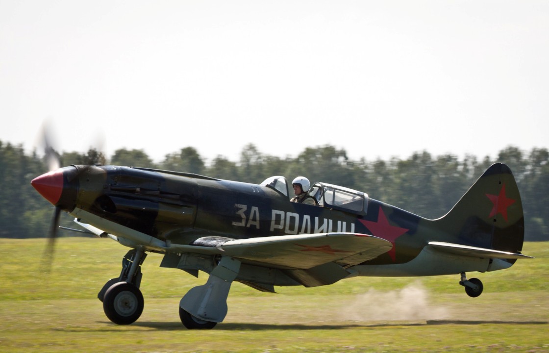
Introducing the contour model airplane MiG-3 world war II, created in OKB led by A. Mikoyan and M. Gurevich.
A little about the prototype. The beginning of the design of high-speed and high-altitude fighter with the factory index-200 can be attributed to 1939. The first flight of the new machine took place in 1940, and began its mass production.
I-200 was a low mixed design with AM-35A engine. The plane had retractable landing gear and had a high aerodynamic characteristics that allow it to reach speeds over 600 km/h and reach a height of 12 000 m. the Aircraft was armed with two 7.62-mm machine guns ShKAS and one 12.7-mm UB machine gun.
After the serial production of one hundred copies of the aircraft upgraded: he’s got a big fuel capacity and, consequently, greater range. In December 1940, the aircraft was assigned the designation MiG-1 — first version-200 and MiG-3 — upgrade.
During the years of serial production were built 3,300 MiG-3.
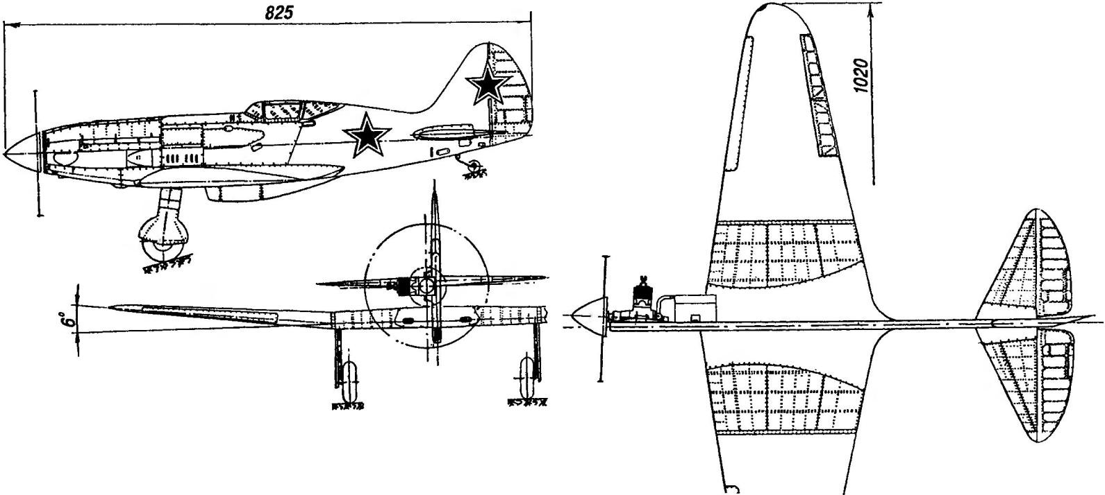
Contour model-a copy of the MiG-3 with the engine working volume of 2.5 cm3 designed by the classical scheme — with flat composite fuselage and a rotary wing.
Contour model-a copy of the MiG-3 (engine capacity of 2.5 cm3; wing area 19,4 dm2; mass of the model 650 g; propeller D = 220, h = 150)
Fighter MiG-3 designed by A. Mikoyan and M. Gurevich (AM-35A engine with a capacity of 1350 HP; length 8250 mm; wingspan 10 to 200 mm; wing area 17,44 m2; take-off weight of 3355 kg; maximum range of 820 km; maximum speed 615 km/h; ceiling-11 500 m)
The fuselage of the model is collected from the front of the plate (plywood with a thickness of 8 mm) and rear (foam PS or PVC of the same thickness). After gluing these parts the fuselage is glued on the contour of the fake reek with section 8×2 mm, and then sheathed with two flat sides or 1 inch plywood, or pressshpana (insulation), or even paper. However, in the latter case, in the area of the frame stabilizer will have to glue the plywood lining.
Is a motor mount glued to the fuselage of a beech wedge-shaped wedges, providing the engine to the desired angle “Vicosa” (about three degrees).
Vertical tail consists of zelenoborskoe keel and stacked (balsa strips) of the rudder. The latter is glued to the keel angle of the neck and degrees to the direction of flight, which together with VEGACOM engine and cargo in the right console provides sufficient tension of the cord in flight. Covering the helm — from a thin Mylar film.
The horizontal tail is collected from zelenoborskoe of lightweight balsa stabilizer and elevators. Relief is in the sample of non-through grooves with the help of miniature semicircular chisels. The hinges of the elevators — classic, sealed “eights” nylon yarns. Right and left handlebars are connected to each other by a wire torsion. Trim elevators and rudder from the same thin Mylar film.
Wing inlaid, classical design. Consists of center section and a pair of consoles. Beam flange and rear flange are made of pine slats, leading edge and ribs from lime. Rib better handle in the package, which requires of duralumin plates with a thickness of 2-3 mm to make templates for the root and end ribs, and then cut into eleven fake pieces, fix them between dural templates with a pair of threaded studs and nuts and process together, first with a chisel and a knife, a Bong, and then a rasp and sandpaper. However, note that the right and left polacrilin under asymmetric wing profile requires right and left packages of ribs.
In the place of fastening of racks of the chassis ribs are cut without relief.
For wing Assembly, it is desirable to use a flat Board-a slipway, securing it is made in 1:1 scale drawing of the planned projection, covered with plastic wrap so that the frame of the wing is not glued to the bench during installation.
Before Assembly, it makes sense to consolidate on the stocks four slats in accordance with the external contour of the wing — this will increase the accuracy of the Assembly. Then on the staple pins and spacers are fixed front and rear edge of the wing, and then the “epoxy” stick to the ribs. Just remember that the end rib of the wing and the root rib of the consoles are mounted is not perpendicular to the slipway as the others, but at an angle so that when docking the center console and the corner of the “V” of the latter was six degrees.
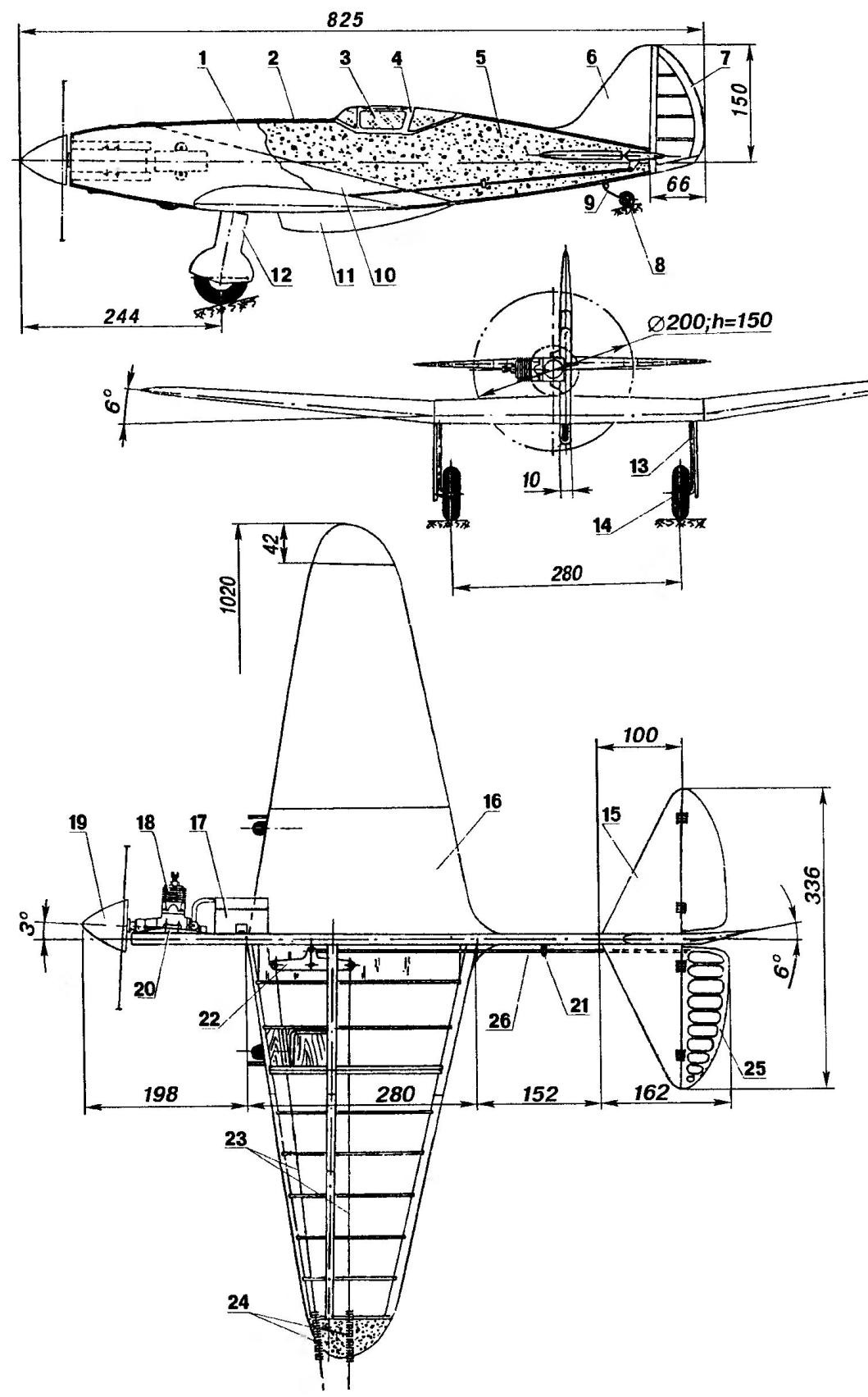
The layout of the model:
1 with the side covering of the fuselage (plywood s1 or cardboard); 2 — piping of the fuselage (basswood, rake 8×2); 3 — glazing lamp (Mylar foil); 4 — cover of the lantern (lime); 5 — rear part of the fuselage (foam PS or PVC s8); 6 — keel (balsa s8); 7 — rudder (set of balsa strips); 8 — tail wheel; 9 — the crutch (the wire OVS Ø2. 5); 10 — front part of the fuselage (plywood s8); 11 — simulation of the air intake (balsa s8); 12 — simulation panel (plywood s2); 13 — main landing gear (wire Ø3, OBC); 14 — wheel main landing (Ø65); 15 — stabilizer (balsa s4); 16 — wing skin (Mylar film); 17 — fuel tank (tinplate s0,3); 18 engine working volume of 2.5 см5; 19 —spinner, 20 —motor mount (beech), 21 — a bracket (aluminium, wire Ø2); 22 — rocking chair control system (duralumin, sheet s3); 23 — the leads management system (twist of two cords); 24 — guide leashes (coil spring with an internal diameter of 2 mm); 25 — the Elevator (balsa); 26 rod Elevator drive (steel spokes)
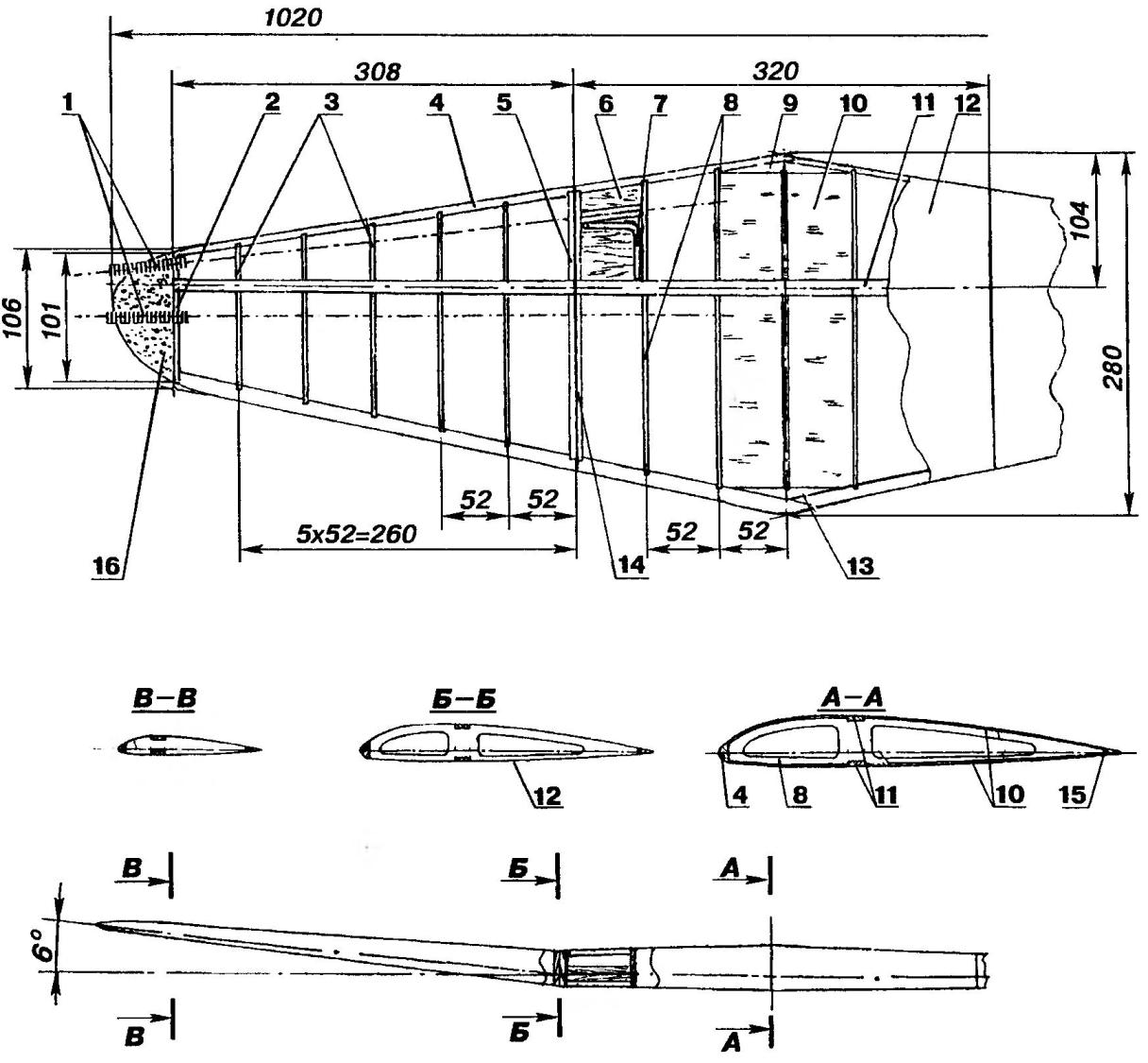
Wing:
1 — guide leashes (coil spring with an internal diameter of 2 mm); 2 — end rib (Lipa s3); 3 — rib console (Linden s2); 4 front flange (lime, rake 6×6); 5 — root rib console (plywood s2), 6 insert (two plywood plates s6); 7 — groove under the front of the chassis; 8 — rib center section (Lipa s2); 9 — strengthening the front edge (pine); 10 — covering the Central part of the wing (balsa s2); 11 — shelf side member (pine, rack 8×3); 12 — wing (Mylar film); 13 — strengthening rear edge (pine); 14 end rib of the center section (plywood s2); 15 — the rear edge of the wing (pine, 10×3 rail); 16 — ending (packing foam covered with fiberglass)
After polymerization of the glue on the wing are installed to the beam flange, and in the middle part of the wing is glued in hard plating of 1 mm balsa veneer. After that, the console separated from the center section, are removed from the pile, are stripped off and butt-glued with epoxy. In the mounting area of the chassis between the ribs are glued packages of a pair of plywood plates and in between the bent parts of the main landing gear. The latter, incidentally, are bent of steel wire, allied with a diameter of 3 mm.
At the end of the right console between the shelves of the spars it is useful to set a lead sinker weighing 20-30 g. the Ending of the console — foam, covered with one layer of fiberglass epoxy resin. For the transaction of governors of the cord in the left tip fixed guides, springs with an inner diameter of 2 mm, made of cords. The wing is fitted by a thin Mylar film using glue BF-6.
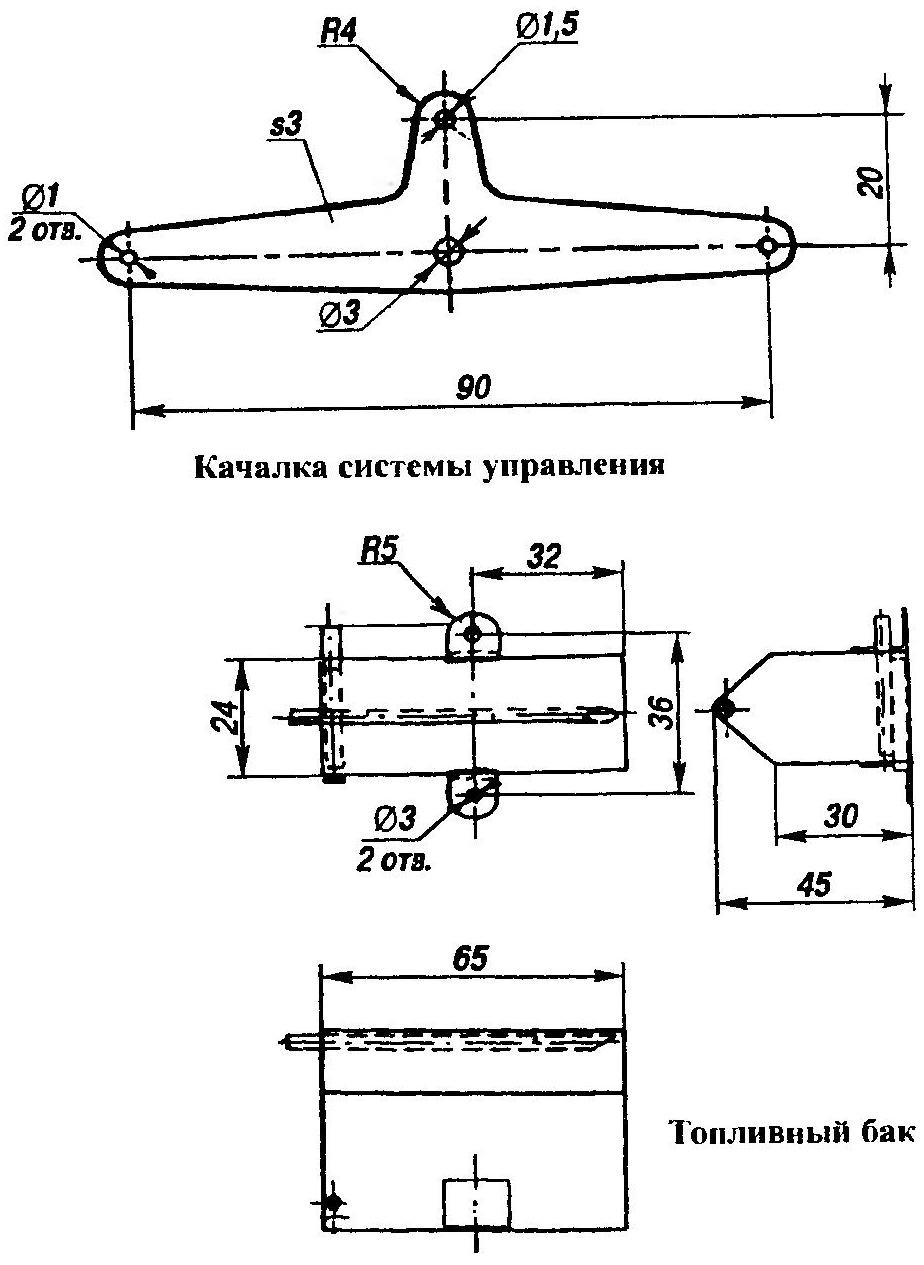
Rocking control cut from 3 mm sheet of aluminum.
Fuel tank tin solder.
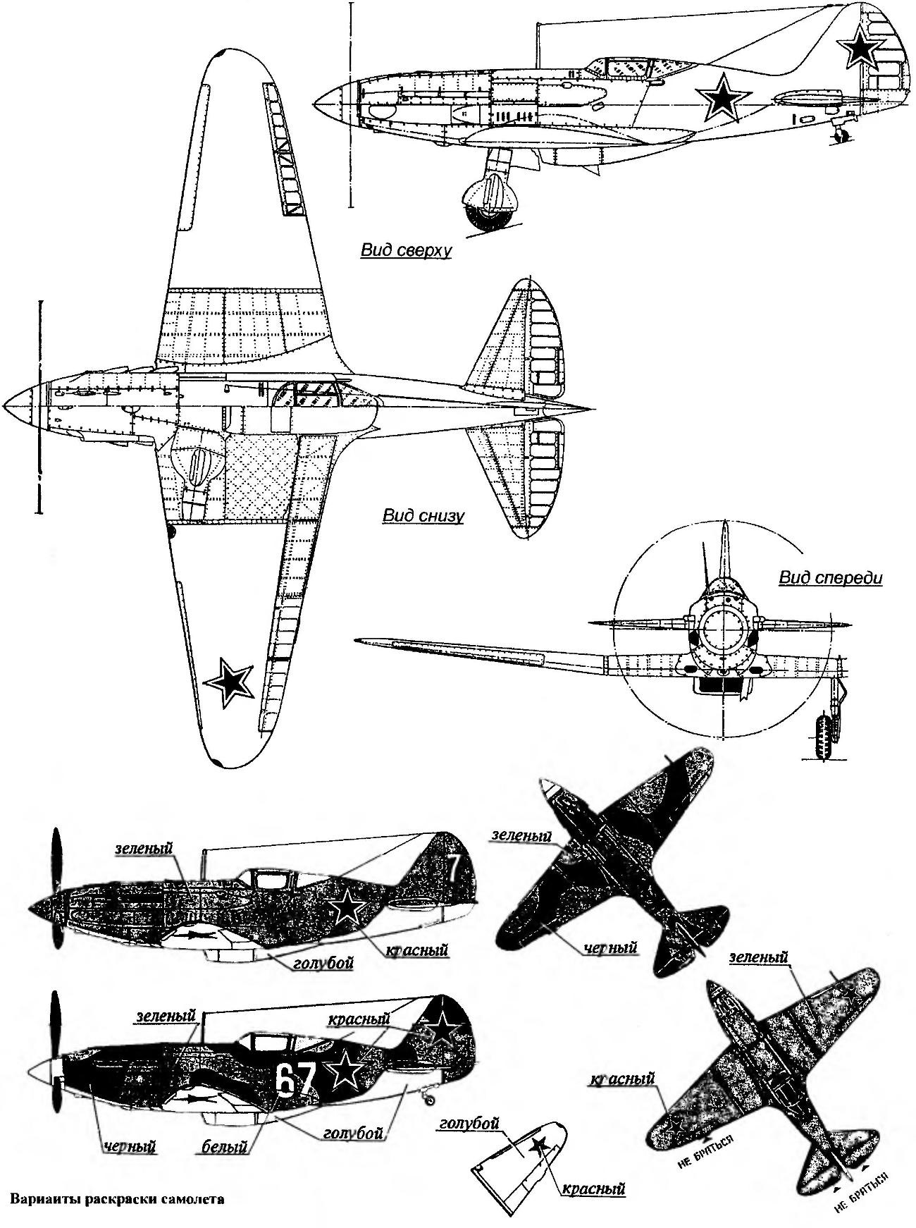
The model is fitted by a Mylar film with painting. It should be noted that the MiG-3 featured a variety of colors, two versions of which are depicted in the figures. When painting a flat fuselage with a spray gun-airbrush make sense to make a “wash-out” from light tones at the top of the fuselage to darker at the bottom — this will give it a three dimensional look. In General, for contour copies of authentic application of camouflage, markings and design elements is no less important than for a full copy.
To represent the joints of plating, rivets, hatches, and decals can be subtle color capillary handles. After this is finished, fasten the trim with a thin layer of parquet lacquer, causing it airbrush.
I. NISTRATOV
Recommend to read
 GARDENER’S SAUNA
In a small utility block on my garden plot, I had a storage room measuring only 2.2x2.7 m. One hot day, the idea came to convert it into a mini sauna and also add a shower section. I... THE CEILING OF LEAVES
Is it possible to make sound insulation of the ceiling? For this purpose, will serve a suspended acoustical ceiling. It performs several functions, it reduces the energy of the reflected...
