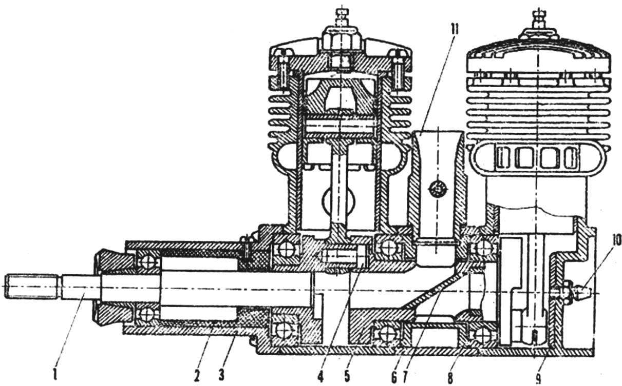
the cushion is carved of steel 30KHGSA (σв— 120 kg/mm2). The work is simple, however, we must be attentive to the bore hole Ø 12 to provide a press fit of the crankshaft. Distribution window obtained by drilling hole Ø 8.8 mm, followed by fine-tuning the channels with needle files. Jumper made of the same steel, has a thickness of 1 mm, exactly fitted to the channel and sealed with solder POS-40. Fillets formed during brazing, not clean — they increase the reliability of the connection and smooth out the corners. The hole for the shank of the neck front shaft is drilled only after the Assembly of all intermediate node.
Spacer — alloy D16T. It and the inner sleeve. These two parts can be manufactured on the whole, however, it is difficult to ensure the alignment of seats under the bearings, and after pressing the rear of the crank node will nonseparable. The Central sleeve can greatly facilitate game polukoltsami the groove shown in the drawing by a dotted line. The distribution window in the sleeve is rendered almost completely, not only reams the upper part to the size of Ø 12 mm — ‘ll do it when assembling the engine. The spacer sleeve must log tightly.
The front shaft is made of steel 30KHGSA. The only feature of his treatment is that the largest diameter is done by the press fit at the front of the crank.
The front of the engine and the front bushing from the material D16T and PCB. These items also can be made integral, but then you have to bore the socket under the front bearing to remove the sock from the machine and flip it over (will need a new mandrel, which can lead to misalignment of the bearings). In addition to ease will need a milling machine.
Overlay threaded carburetor is also made of aluminum. The nozzle from the serial engine, as well as support washer air screw clamping cone. Fungus of steel 30KHGSA.
The Assembly of the motor starts with the front hub. First aprecaite ready made crank on the shaft. Insert the front bushing in the toe, install the shaft with the bearings. If it easily rotates and has the required axial play of 0.1—0.2 mm, locking bushing, nasverliv and cut into the slot under the screw.
The most important step is assembling the Central unit. If you have already shortened the finger to the back of the crank to 6 mm, by checking using measuring instruments the resulting axial play (also he should be 0,1—0,2 mm), you are ready to press fit the crank. Don’t forget to wear the roller Central sleeve and bearings! From the back, the angle between the axes of the finger and a distribution window in the platen is 45° ± 2°. After putting on the spacer, check the ease (.occur in the bearings. Adjust the position of the sleeve, providing the required phase suction, drilled a hole under shtorku the nozzle to 12 mm. Left accurately mark and drill out the socket under finger the front of the crank.
Reducing the thickness of the BOTTOM heads of rods up to 6 mm, set futerko and assemble the entire engine. Assembly is best done on the polished tiles, which are pressed against the foot of Carter’s. Again measure the received timing.
Absorption phase for each cylinder: the beginning — 45° after bottom dead center of the corresponding cylinder, the end — 45° after top dead center. Checking the ease of rotation of the shaft, the volume of the combustion chambers (they should be the same), you are ready to run. It is no different from running a regular “odnotrahniki”. Screw size 320X150 mm, the fuel contains 30% castor oil.
The weight of such Sparky is equal to 390 g (without muffler and screw).
Finally I would like to give advice concerning the manufacture of all parts. The serial elements of the engine design process only on the mandrels, and the new furbish with one Ushakova! The only exception is processing of lowering one of the ends of the Central sleeve — here the accuracy will not affect your “tenth”.
V. SALANECK, master of sports of the USSR
Recommend to read
 IN THE DESERT — SAILING
Wheeled Buer, beach sailing, sand yacht, metromobile... All these terms refer to the same Tina of vehicles using the movement force of the wind. Designs of such "petroholod" — a great... AND THE CARGO ON THE TRAILER
When there is a need in the trailer for transportation of household goods, there is the problem of choosing which trailer to buy, good this choice was. That's the only difference in...
 Conceiving a new microplane, any Modeler primarily decides which engine to put on it. One of the motors power is not enough, others too large, others strongly vibrate during operation. Many disadvantages of single-cylinder engine delivered a two-cylinder of the same displacement. They can be built on a variety of schemes: boxer, Y-shaped, inline. In some cases, if the Modeler is not very important weight, two normal “odnotrahniki” mounted on a common metal frame, connecting the shafts through the gear transmission. This allows to raise efficiency of the propeller by increasing its diameter at low speed.