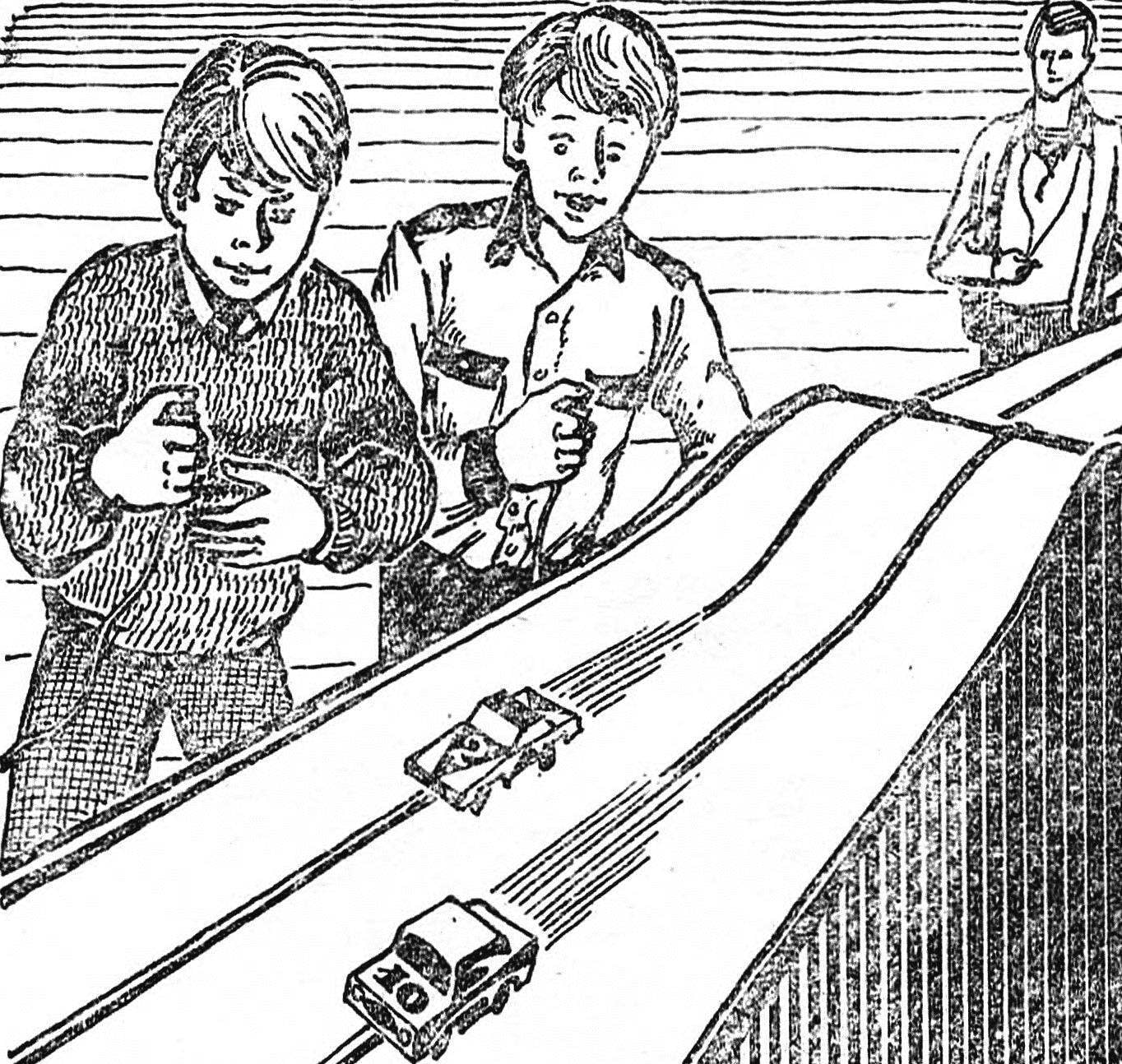
 For ten years the laboratory simulation of young technicians station in Rostov-na-Donu spends on the road forty-meter competitions. They involve teams of clubs children’s clubs when Dezy. The program of competitions on the Cup includes a sprint race on 40 m marathon race PA 120 m and team relay 3×40 m. the Struggle is literally for every fraction of a second. To win a race is not easy — models young athlete will have to overcome steep climbs and descents, sometimes combined with twists and side bends, a flyover and the areas where the throws like on the cobblestones.
 For children such competitions is not only a fascinating and addictive game. It is also a school purchase konstruktorska skills, sportsmanship, character progression, the first step on the way to the “big” route to modeling. And it is especially important that this path is opened for the children of primary school age who are engaged in the circles of primary technical modeling. Device models-polycopy easy to build and manage the school in the design there are no scarce materials.
As time has shown, sports and technical competitions significantly enhance the work of groups in the community. In favor of such slopes is confirmed by the fact that, in addition to the monorail “track” syut, these tracks are now in the seven districts of Rostov-on-don.
DESCRIPTION OF THE ROUTE
The basis of the route may serve as construction plywood with a thickness of 4-5 mm or hardboard. The latter is preferable because fiberboard does not warp and crack over time from stress on the bends. To provide better traction model with the “path” to the working surface used the textured side of the plate.
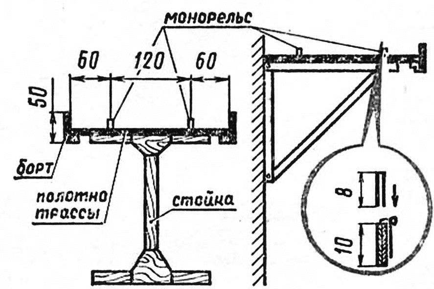
The installation of blade alignment:
Left display” | mounting ;base on a wooden stand, to the right of the PA metal or wooden square .
Steep and sloping hills, overpasses, areas with transverse slopes of the form, lifting a cloth on a solid wood or assembled from metal parts of the support. Plate or plywood fixed with nails and glue to the corners is fastened with screws with countersunk heads. Rigidity reinforced sides keeps off the tire model from falling off the track. The Board is made from the same material as the canvas, and attach it to Pradelna rails or corners.
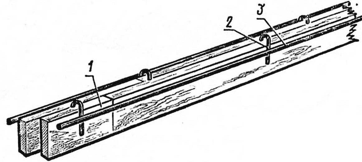
The monorail:
1 cardboard element guide 2 — u-bracket-bus,3 — bus conductive.
For the rail monorail mm cut from cardboard strips with a width of 10 mm. best thing to do is a sharpened knife along the ruler. Separate cardboard details link on the PVA glue in two layers, with the joints of the strips right and left side move relative to each other by 30-35 mm, then to the ends of the “links” you can connect the overlap. Marked out on the track the middle of each track, set the markup cardboard guide rail and pin their pins. In places vertical curves of the track in the blank with scissors, make vertical cuts with depth up to 6 mm on the climbs and the descents down at the tops of the curves are on top.
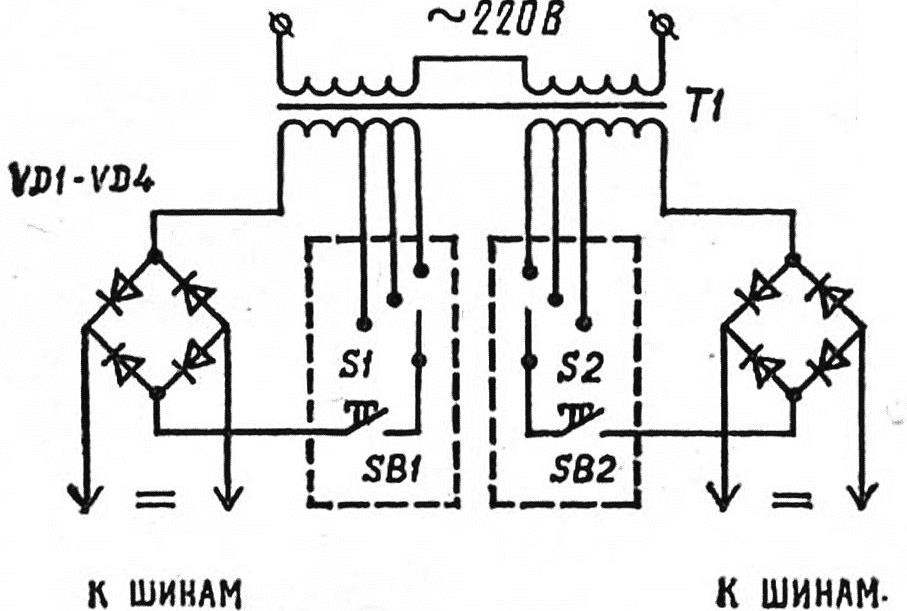
Electric circuit
Finally installed the guides, double-coated with a liquid glue, after it dries the pins are removed and the base color the color of the roadway, and white paint applied to the boundary line. For fixing busbars made from copper wire with a thickness of 1 mm without the insulation, straightened paper clips, harvest brackets-brackets. Thin awl puncture a hole in the rail at the junction of the two layers, insert the bracket, compress the pliers and top fixed with a drop of glue. The next bracket put on the other side of the rail. The distance between the points of the busbars must not exceed 50 mm. the Current-carrying wires are soldered to brackets at the upper edge of the rail, the joints of the tire — lapped, with propanol connection and subsequent Stripping with a file.
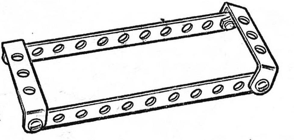
Chassis frame assembled from parts designer and prepared for soldering.
The power supply consists of a dual track highway type transformer T-100 two rectifiers, assembled on the diodes of sufficient power, for example, D 243. Both calipering transformer winding is placed in two coils, connect the jumper, and instead of removing the secondary winding coil of new three sections of 11 turns of wire PEL 0 1.0—1.5 mm. Transformer and rectifiers, closed housings, mounted on a support base of the track near start / finish. Remote control panels connected to the power supply twisted wires. The rectified voltage is applied to the tires of the missing through the holes in the base and soldered the wires to the brackets.
DESCRIPTION OF THE MODELS
The car that the young athletes take part in competitions, divided into three classes: A — maps B — buggies, cars, and experimental cars.
The frame map is assembled from parts of children’s designer. Two straps with eleven holes (hole pitch of 10 mm) and two cross-braces with the holes in the 1-3-1 scheme are held together with screws, after propane connection them. Side safety arc bend wire (Cycling or knitting needles) and also soldered to the frame.
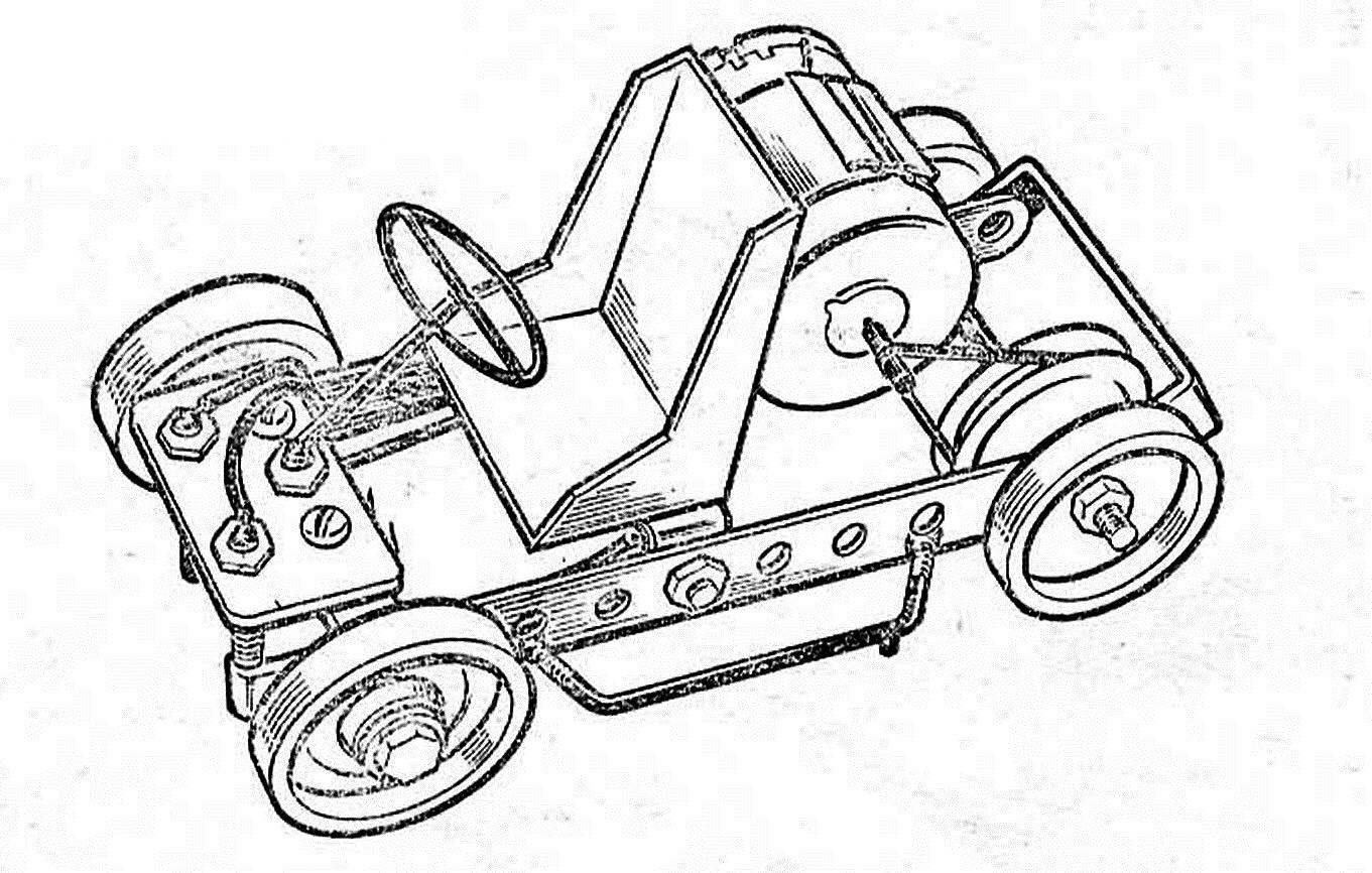
Model card, move-in ready
Wheel members in the club make… checkers! To accurately drill a hole in the center of each checkers helps the liner conductor, indispensable in “production” of model production. Tyres is a ring with a width of 10 mm cut from Velocimetry and fixed on the rim with a rubber or glue “Moment”.
The front wheels are free to rotate on the screw — rod length 15 mm. Hubs serve as washers, glued on the epoxy or the “Moment”. If given the opportunity, it is better to stick in the wheel a small ball bearing. The connection node when assembled, gently RUB a small amount of glue. Then, even during long-term operation models the wheels will get loose.
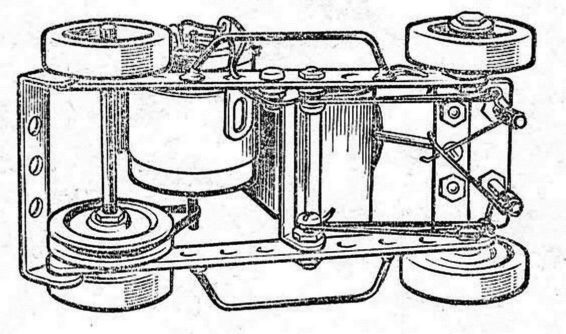
View of the chassis model from the bottom.
Delays of the current collector in the case of installation on the road to divorce in different directions.
Rear axle — smooth rod d 4 mm and a length of 65 mm. Such parts is in the children’s constructor, you can use a knitting needle. On one end of the shaft is cut a M4 thread length 10 mm, on the opposite 30 mm of Plexiglas or plywood with a thickness of 5 mm is cut sheave working ø 28 mm, exactly in the center drilled hole and the edge of the triangular file propisyvaetsya the groove for the belt transmitting rotation from the engine to the rear axle. The rubber belt, rubber ring with a width of 2 mm is also cut from the old Velocimetry.
The Microdrive is mounted on the frame area of the surface, and the clamp strip of tinplate of a width 29 and a length of about 100 mm. the ends of the strips are bent so that the motor housing can be securely fixed, with clamp, in the middle of the strip is soldered area. After wrapping the engine clamp the ends pulled together by thin copper wire. On the shaft of the electric motor is cut beveled with wire insulating tube. Then the engine is screwed to the frame.
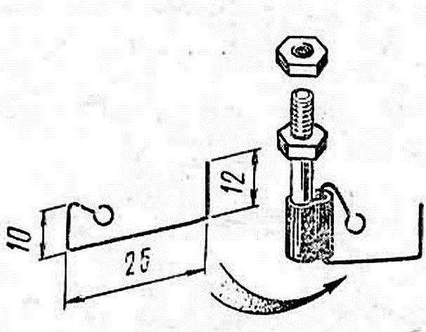
Stand with the current collector, one pole of the supply.
Of the PCB or Micarta thickness of 2 mm is cut plastic 20X40 mm with three screws and extends to the front bracket to the crossmember of the frame. In the middle screw is fixed by soldering simulation steering column with the steering wheel. Approximately in the middle of the frame is set one jumper, which is located a cardboard seat “racer”.
Additional front holes of the insulation plate are inserted into two guide posts with a length of 30 mm. Their saw off the threaded studs included in the set constructor, or cut the threads on the pin d 4 mm. the current collectors are bent from spring steel wire d 0,6—0,8 mm, hinges for them — of tinplate. Holding the loop with pliers, they are soldered to the uprights. The gap between the struts and the plane on which the model should be minimal. The reliability of the contact between the current collectors and the current-carrying tires is provided by the compression of the wires by winding of rubber threads. Their tension is regulated by a wound on the screws of the seat. The findings of the “brushes” on the back cover of the electric motor soldered flexible wires. They connect the engine to the uprights.
Model Buggy
Frame “buggy” cars and автоvобиля in design and the pattern is repeated model map, and their bodies are made of thin cardboard or drawing paper. It all depends on the imagination of the younger autoconstructor.
E. RYABCHIKOV, Rostov-on-don
Recommend to read
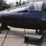 “PYGMY”, “SIREN”, “TRITON” MADE IN THE USSR
In 1921 - 1939 in Leningrad acted Special technical Bureau for military inventions (Sptecbureau), it was headed by engineer V. I. Bekauri. In 1934 in a 1st division Sptecbureau was...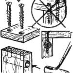 RELIABLE CONNECTION
It is well known that the screw is well fixed in the tree if he wrapped it across the grain. Wrapped up in the end boards, he quickly becomes loose and eventually falls out. To make this...
