Deserve attention and the ending. Bent down and increase the radius of your bend when approaching the trailing edge, they also reduce the intensity of harmful trailing vortices.
The root portion of each of the consoles will draw up plans a number of ribs of increased strength. Through them will pass the pins of the hinge wing on a large scale, creating significant bending moment in the seal. Usually applied two-pin linkage, here is not superfluous and a third node. The wire diameter of the pins — 3 mm, their length — 210 mm. In a pinch you can use a steel grade optical fiber, but it is better to specifically make and termoobrabotki pins of steel khvg.
So, let’s begin. Cut with the maximum available precision of the templates from sheet duralumin, handle between them of a pack of ribs for the wing and the ears. The first five, installed in the root of each console, polutorametrovoy made of plywood, the rest is balsa of different densities (at the ends of the wing ribs from light wood) with a thickness of 2 mm. Prepare the trailing edge (balsa section 12X4 mm), tapering from the crest consoles to the ends of the ears, and the pine shelves spars of variable cross section. Their width decreases from 10 mm at the root to 2 mm at the end of the wing. Thickness top shelf in 2.5 mm, bottom 1.5 mm Additional longitudinal pine, the cross section of the strips changes from 8X2 mm to 2X2 mm. balsa cross-section of 4X5 mm cut front edge. In the root plywood ribs for additional template drill holes Ø 3 mm pins.
THE COORDINATES OF THE PROFILE OF AL/33
If you are ready the main elements, we proceed to the Assembly. It will certainly spend on the Board-stocks, marked out on the surface position of all the longitudinal and transverse set. Glue the main frame, and put under the edges of the slats wedge shim that sets the required wing twist. It should be like this; a fracture of the right console + 2 mm of the leading edge; the center-console left untwisted; the ends of the consoles + 3 mm of the trailing edge. Endings exhibited relatively fracture the console, the center section is relative to the root section. The specified deformation of the planes provides debugging planning in the right turn. Install diagonal spouts and tail oblique polonaruwa, giving the frame a considerable rigidity.
Now it is the wall of the spar and tight “forehead” wood. For plating, you will need light balsa with thickness of 1 mm. Carefully fit the sheets to the front edge and shelves of the spar, and then, without removing the frame from the pile, insert the upper part of the casing in place. The bottom set removed from the Board wing, immediately after that it once again fixed on the slipway. After the glue is mounted pine plate leading edge is sheathed with balsa root area of the wing, stick the root end rib, cut from plywood in the thickness of 1,5 mm. In General, the wing was ready. Remains Pro-skins frame and covered his thin long-fibre paper. Secured on the staple portion of the consoles have to stay on it for at least a month, only then the probability of random curvatures of planes will be reduced to a minimum. Carefully adjusted to each other’s ears and the center section, made separately, are joined with epoxy. The front part of the seam is helpful to strengthen prillerova scarves, carved out of the finest fiberglass.
The stabilizer has a PLANO-convex profile with a relative thickness of 6%. As shown, this horizontal tail corresponds to the alignment model, 54% of the chord of the wing. If the glider is reluctant to gain altitude after an energetic dynamic start, we can recommend the thicker profile of the stabilizer (although valid and forward shift of the center of gravity while decreasing the angle of attack of the tail). If the model nose up sharply and slowed down, the center of gravity is shifted back with a corresponding change in the position of the stabilizer or on the latest used lenticular (up to symmetric) profile.
The horizontal tail must have a minimum weight, so all its elements pick up a light balsa. Ribs are cut from millimeter veneer, the trailing edge has a cross section of 2X8 mm, front — 4X5 mm and the spar — 2X5 mm. If finished, covered with paper stabilizer weighs 8 g, so you managed to do it excellently. The Central part of the edges after pasting enhanced by bamboo splinters. The stabilizer mounted on the keel pad with front and rear nodes.
The rudder is unconventional. The main purpose of this layout is to release the stabilizer from damage when landing from parachuting and increase the effectiveness of the vertical stabilizer without changing its area. Manufactured stacked with a shell of a simple frame mm balsa veneer. After finishing the exterior trim from the keel is cut and the hinge is hung on the rudder, is glued platform bed stabilizer and mounted the power steering servo and control linkage lift edge of the horizontal stabilizer when switching to parauterine.
When working on round the tail boom of the fuselage, with a retinue of mm thick balsa and covered with fiberglass with a thickness of 0.04 mm, follow the culture weight. Light tail section of the airframe — the key to a steady flight even in gusty wind.
The nose of the fuselage (top) and keel design.
The nose part is cut in two parts lime, and after preparation of internal volume that conceals the hook-machine dynamic start, the clockwork timer and the camera with partial load tion of the ballast is glued together and is covered with fiberglass with a thickness of 0.1 mm. then glued the plywood connecting ribs are inserted pins and wear parts fixed brass balance weight. Ballast is also used POI accurate adjustment of the position of the center of gravity of the model and refining its mass to the required rules 410 g (with a better warranty, a little more than a — 412 d).
On the wing across the span at a distance from the leading edge to 5% chord on the upper surface of the thread is glued to the baffle with Ø 0,6 mm.
Hook-machine dynamic launch model with the similar design as described in the journal “modelist-Konstruktor” No. 3 for 1976. The force required for opening the latches of the ring rail, equal to 3,2 kgs.
DMITRIYEV
Recommend to read A CHAIR FROM THE MATTRESS When the child grows out of cot, its mattress can be used for making original floor chairs without legs and frame, it meets the teenage spirit interior. Chair-mattress is placed... VENEER DO During the construction of the models is often necessary to apply a veneer of varying thickness. Typically the desired thickness is obtained by grinding with fungus with glued on end... 
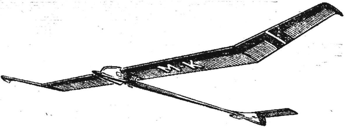 What models of gliders was not in the sky above the sports airfields! Short-tailed side by side with these, whose stabilizer it seemed unreasonably far related from the wing, the search of the optimal elongation of the supporting planes of the transformed outline of the airframe in the likeness of a flying ribbon, brachypterous, such aircraft unit. A few years ago, athletes arrived to a common opinion. Although each scheme had its own advantages and disadvantages, experimentally found the best dimensions that satisfy the conditions of soaring in thermals, the flight in a calm atmosphere and in a strong wind. Parameters recognized compromise (wingspan 2000 mm, chord 145-150 mm, shoulder 700— 740 mm), provided smooth, very good results.