The attention of many modelers are attracted to the photos (“M-K”, No. 10, 1979) on the international competition teams of the socialist countries on aviamodelling sports. The editors have received many letters with the request to give more details about the model of the winner of these competitions the master of sports of international class Anatoly Kolesnikov from Frunze. To fulfill these wishes. L. Kolesnikov talks about his Cordoba flight.
When designing the cord aerobatic model aircraft has to solve a range of problems in search of a reasonable compromise between parameters such as stability and handling. The fact that the basic requirement for pilotage — high maneuverability when the figures with a large margin of stability in horizontal flight. As a rule, “connect” these conflicting requirements is possible only when taking into account the individual qualities of the athlete, his inherent piloting technique.
A simple example. If you have been trained in piloting models having a higher gear ratio from the control handle to the handlebar height, it makes no sense to switch to less sensitive controls, borrowing a good, but non-aerodynamic design.
For the model of the conventional scheme (flaps and Elevator) criterion sensitivity control can be considered as the ratio of the variance of the control stick and the appropriate steering. For example, if the handle at a certain angle causes rotation of the steering surface at twice the angle, then we say that the sensitivity control is equal to two. Have ceremony models, these values are in the range from 1 to 2.5.
Optimum sensitivity of the control flaps is 88% from the same setting of the Elevator control.
The aerodynamic layout issues. Each athlete usually develops a whole system of knowledge about the influence of the geometric parameters of the model on its flying qualities. When developing a new model takes into account the sensitivity of the controls of the previous, and based on this determines the capacity, the weight of the model, the specific load chosen, the area of the wing and horizontal tail. After that you can proceed directly to the layout.
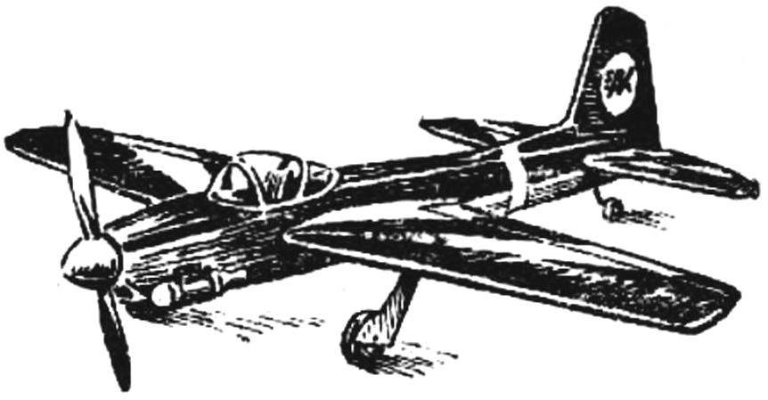
Fig. 1. Control line aerobatic model A. Kolesnikova.
The layout of the fuselage. When performing complex maneuvers the fuselage of the model is constantly in sight of the judges. It makes carefully selected to its contours, giving the models is not too rapid form. It is also important that cabin, spinner and wheel dimensions the chassis has been commensurate with the size of the layout of the pilot.
Layout of the wing and horizontal tail. The maneuverability and stability of the flight and mostly depend on the proper selection of wing parameters — elongation, contraction, sweep, the relative profile thickness, and the location of the stabilizer relative to the aerodynamic focus of the wing.
As shown, there are several solutions to the optimal selection of these parameters. So, for example, to increase maneuverability, you select the wing with slight sweep, decreases the removal of the engine and the horizontal stabilizer (i.e., decreases the spacing of the masses), used the wings of large aspect ratio.
High maneuverability is also provided by the offset center of gravity back with a simultaneous increase in the area of the stabilizer. This aerodynamic configuration is inherent to the models of American athletes.
Fig. 2. Kinematic diagram of the control system
Because resistance is the reciprocal of the handling, increase first facilitated by the steps opposite to the above and to increase maneuverability. The optimal ratio of stability and controllability is selected by the athlete during the design of the model and the test flights.
Choice of unit load. Load, related to the total wing area and horizontal tail, typically ranges from 27 to 32 g/DM2 . If the model is operated with Korda with a length of 17-18 m, the load should not exceed 28-29 g/DM2 , and the length of cords 20-21,5 m — 30 to 32 g/DM2 .
Aerodynamic and static balance. From them depends largely on the quality of the flight model. For the load balancing model provides the mounting point for the cargo located on the consoles of the wing and the rear fuselage. Structurally, they represent a sleeve with inner thread M4 or M5. For the same purpose on the inside of the console Assembly is provided that allows you to shift the holes of the withdrawal cord of the wing.
The design of the model. From all I have previously built model and drawings which is now in front of you, seems to me to be the most successful. Its characteristic feature is the location of the axis of the engine, the chord of the wing and horizontal tail construction the horizontal fuselage. This ensures the same angles of taper of a stream entering the stabilizer under both normal and in reverse maneuvers.
The wing is single-spar. The side rail has a variable cross-section: 3 X 7 mm At the root and 2.5 X and 4 mm at the end. The necessary strength to provide a wing wall is glued between the butt of the spar. Ribs carved from balsa plates 2.5 mm thick, lightweight and are reinforced around the perimeter of the shelf. The front edge of the wing is covered with a veneer thickness of 2 mm, it allows to strictly maintain the profile and between the ribs.
Along the rear edge across the wing span are differentially deflected at angles of +30° and +34° flaps. They are cut from the balsa inserts and banded pine lath thickness of 2 mm.
The stabilizer, elevators and fin are also made of balsa with a density of 0.09 g/cm3 . The area of the elevators is 65% of the area of the horizontal tail. Limit angles of deflection of the rudders +45°.
The model has a two-wheeled chassis with a tail wheel. For easy transportation the main landing gear is made lacosamide.
When finishing the model used was a synthetic and polyurethane paints.
The power plant has a self — made engine with three-way purge. The working volume of 7.5 cm3 . Fuel system engine has automatic stop actuated from the dash with the control stick force 15-17 kgs.
I hope that my development will be useful for modellers dealing with pilotscale, and will help them in designing models of their own design.
Recommend to read “HELLO” — “MOSCOW” I homebrew with years of experience, have built and snowmobiles, and ATVs. But my biggest passion is boats. Despite today's gloomy everyday worries, I still find time to do what you... FROM BIPLANE TO MONOPLANE Carrier-based scout CURTISS SB2C HELLDIVER. In early 1938, the Bureau of Aeronautics of the U.S. Navy has developed the conditions of tender for the construction of a new deck of... Scroll back to top

 The attention of many modelers are attracted to the photos (“M-K”, No. 10, 1979) on the international competition teams of the socialist countries on aviamodelling sports. The editors have received many letters with the request to give more details about the model of the winner of these competitions the master of sports of international class Anatoly Kolesnikov from Frunze. To fulfill these wishes. L. Kolesnikov talks about his Cordoba flight.