Interesting question about the ratio of the geometric parameters of the tube. Often athletes modelers are given in the literature data, practically without analyzing them and paying attention to the contradictions in various sources. It appears that the new methodology will allow to clarify the actual characteristics of any resonance of the exhaust pipes and compare them.
The first option — the removal of the pipe resonance curve with the generator frequency sweep (sweep) with changed parameters “saw” 40…50 Hz and the sweep fср about 1500 Hz. It uses the power amplifier TO 237 UN, IC output through the earpiece TONE 1 is connected to the input of the coarse, and the exit —DAMS on the oscilloscope. Sync — with “saw.” Voltage stabilization is required. Including sweep and selecting the parameters of the experimental setup, we achieve the appearance on the oscilloscope screen resonance curve. An example of a specific test can serve as a photo from the oscilloscope screen (see Fig. 2, 3, 4).
The second method allows for experimentally derived results to determine the efficiency of the pipe. For its implementation of a piezoelectric emitter of the alarm clock made a dynamic pressure sensor. At the side of the radiator, drill a hole 3 mm in diameter and carefully soldered the copper tube of external diameter about 2.5 mm. the terminals of the sensor is filled with epoxy resin. Case grounded sensors and the Central output connected respectively to the first and second channels of the oscilloscope. The input “X” to connect the microphone to the type of DEMS to run in the “single pulse”. Set the pipe on a wooden plate, then the entrance is attached a pressure sensor and a microphone (second channel) and the input “X”. On the outlet pipe to mount a second pressure transducer connected to the first channel. The phase shift must be equal to zero. Scan from 2 to 5 MS, the first channel is from 0.2 to 0.5, the second — 1.
Then at the entrance of the tube set a firecracker that you can buy as a set-Union of elements of red and green color with a diameter of about 2 mm. in Front of the screen of the oscilloscope place the camera with the cable release and exposed the “infinite” exposure, charged film “Photo-100” or “Photo-250”. Set fire to the firecracker and press the camera button. When the explosion created a shock wave, which gives the corresponding picture on the screen of the oscilloscope. The time of the film must be equal to 12… 16 min., positive prints are performed in the usual way.
We are interested in the efficiency of the pipe is determined by results of processing of pictures (see Fig.5) according to the formula
where a1 is the amplitude of the first pulse, and2 the amplitude of the second pulse (regardless of the scale of the photograph).
I think that would be interesting to know that the efficiency of the resonance of the exhaust pipe of the engine “Rssi.15Fi” equal to 25…30%. An example of processing results on the images — Fig.5.
The third method allows to make a kind of certificate of quality of the pipe. To implement this method, the pressure sensor placed on the outlet pipe, and a microphone at its input, by connecting it simultaneously to the input “X1” of the oscilloscope. Scan 6T — 2 MS. After receiving pictures determine the ratio of the amplitudes, divided by the period 5T (that is, given the sweep time). It remains to find the characteristic of damping vibrations according to the formula
The smaller C, the more is the vibration amplitude at resonance.
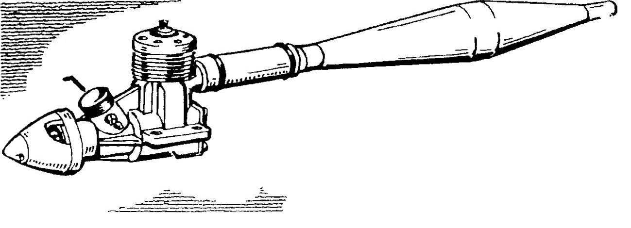
 In the magazine we told about the methods of choosing the parameters of the resonant pipes (“modelist-Konstruktor” No. 9 for 1995) for highly accelerated engines. Fulfilling the wishes of modelers, editors have been asked to continue this theme of the master of sports V. Fontecha from Cherkassy (Ukraine). As you know, at the time of opening of the exhaust window motor is formed as the shock wave represents the process of propagation of a pressure pulse with velocity V=20 sqr(T) (T — exhaust gas temperature in OK).