
 In the early 70-ies before the Soviet athletes-automodellista was a challenge: dvuhsotmetrovy to exceed the threshold speed in the class of models 2.5 cm3. These days, the speed has mastered many of the leading athletes. A sharp jump occurred in 1973, when during the season a few models exceeded the speed of 220 km/h.
This became possible mainly thanks to the transition to the new three-way purge system of the engine and the use of resonance tubes on the output. Engine power increased to 0.8—0.9 HP This, in turn, presented to the models new requirements. Such power should be able to use. It happened that when the output of the motor to the operating speed model was losing grip with cord track, the wheels started to slip and the speed was drastically reduced.
To provide high-speed models currently used enhanced suspension master and slave bridges, and also vibration absorbers (dampers). Increased length models. In an effort to reduce the midsection, many modelers have removed the slave and even the drive wheels to the body. The model has gained a more streamlined appearance.
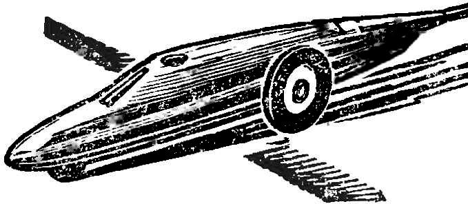
Today we introduce a model that has worked well as on intra-Union and international competitions.
At the European Championships in 1973 in the city of Cantanhede (Germany) she took first place and set a world record 220,426 km/h. Model meets all modern requirements and has not yet exhausted all its possibilities. In future work it is possible to achieve better results.
The following is a brief technical data model and manufacturing technology of individual units.
The weight of the model — 1150
Length — 450 mm.
Base 248 mm.
Height — 75 mm.
Track width — 70 mm.
The engine is a homemade, three-channel, with the resonance tube.
Bearing part of the body (pallet) is cast from aluminum alloy AL-19. This alloy is well handled and gives a smooth shiny surface. It has high mechanical properties. The model for casting are made from basswood with the observance of linear angles, and allowances for further machining. Casting was carried out in the ground. Special attention should be paid to the milling of the base surface for mounting the engine and drive axle. This work is made with a single setup on the machine, otherwise the possible distortions that lead to unnecessary mechanical losses in the transmission to the wheels.
Drive axle is a step-down bevel gear. It is equipped with a pendulum suspension. The role of the shock absorber performs coil spring Ø 8 mm, is wound from wire Ø 0,8 mm. the Spring is placed in a steel Cup. Shock master and slave bridges are similar.
The gearbox is the most complex machine, and how exactly it is done depends largely on the final result shown by the model. The gear case carries the large radial And lateral loads, so it should be made of steel or material, not inferior to it in strength, for example alloys of titanium. The housing consists of two halves. The plane of the connector passes through the axes of the bearings. This gearbox design is very convenient for assembling and debugging. In the manufacture of the gearbox housing are made in the first two blanks of the same thickness. Mating plane of the polished or lapped, then drilled the holes for the guide pins Ø 2 mm screws M3. Then in one half zapressovyvajutsja studs, in the other they have to log in with a slight effort. Then tapped under tightening the bolts, and both the workpiece screw. When they bonded, you can begin to bore nests under the bearings to be performed on a lathe. For this purpose one of the side surfaces is adopted for the base and exposed on the indicator.
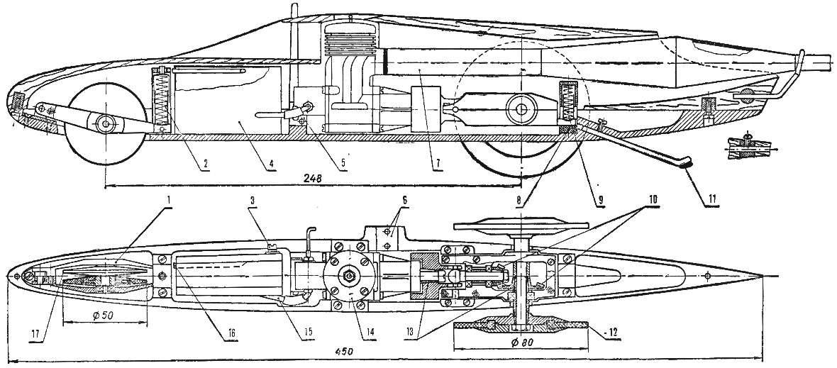
Model:
1 — rocking chair slave bridge, 2 — absorber of the driven axle, 3 — filling hole with screw – – tube, 4 — fuel tank 5 — stopping device 6 — slot and mounting holes and a cord strap, 7 resonance tube, 8 — deflection limiter of the suspension (porous rubber), 9 — absorber axle, 10 — pinion gear 11 — carbide brazed, 12 — drive sprocket, 13 — split tapered bushing 14 — motor (own designs), 15 — a feeding tube, 16 — drain pipe, 17 — front wheel welded disk.
The deviation indicator should be not more than 0.01 mm. the Plane of the connector should coincide with the axis of the bore, which is also verified by the indicator. The housing bore is best to start from the end of the reducer, that is, from the axis of the small gear. Then detail unfold in the Chuck of the machine 90° and put on the base surface of the indicator is similar to the previous operation, and then chiseled the preliminary through-hole Ø 10 mm socket under one bearing. The nest under the second bearing chiseled on the mandrel. After that you should drill a hole for the axle shaft mounting the reducer to the pan and make a selection window for the gears, and also facilitate the gear case. The axis of the reducer are made of steel 12KHN3A, termoobrabotannyj with the subsequent polishing. Transmission of engine torque to the gearbox is made through the ball of the gimbal. At one end of the minor axis is made a ball with a hole in which the press pin Ø 3 mm. the latter is to use a roller from a needle bearing of appropriate diameter and length. Spacers for small and large axes made of steel. In the manufacture you should pay attention to precise adjustment of their length. Otherwise there are large loads on the bearings, leading to unnecessary mechanical losses.
The gears used in the gearbox, are respectively 14 and 27 teeth. Gear ratio 1:1.93 and. The module of the gears is 1.0. To make such gear possible only in conditions of production. On the axes of the gear are fastened with split taper bushings, machined from brass L-62. This position ensures accurate and secure installation of gears.
Much attention should be paid to the gear Assembly. Axis or customize pre-grind fine sandpaper to the bearings, so that they would sit on the axle with a slight effort. Bearing housings also finally lapped. Landing in the nest is chosen empirically. Used 6X15 bearings 5X13 and is very sensitive to stress: an excessive preload can lead to their destruction. Installed in the gear case axis should rotate easily. Only then can you proceed with the installation of gears. Gear should be easy, without bumps and knock to run in with the smallest gap. Big gap between the gears increases their wear.
V. POPOV, the master of sports of international class
Recommend to read
 B-25 “Mitchell”
During the great Patriotic war in the Soviet Union from the United States and supplied under lend-lease twin-engine bombers b-25 "Mitchell" company "North American". The aircraft started... CLOWN RUNNER
Among the "walking" toys that kids love to haul on the rope or to push in front of him, the most attractive dynamic: if any item jumping, waving, jumping or rotated. These qualities, it...
