 The desire to create something unusual and striking, inherent, perhaps, to each of the modelers. This made sense at the time to try to find a new class of radio controlled gliders, which after years of occupation began to seem quite similar. Some time ago on paper there were projects non-motorized flying wings unusual geometry and several gliders-ducks. However, knowing that the process of creating a glider of any class more demanding than the aircraft, did not want to go on a risky experiment – flight properties of such extravagant cars were unpredictable.
To decide on the end design and build “ducks” helped the information from the last world Championships, which were athletes with the “canard” timername models. The competitions of such high level with such machines managed to get up to additional rounds! Of course, this fact added enthusiasm and work on a radio-controlled glider boil.
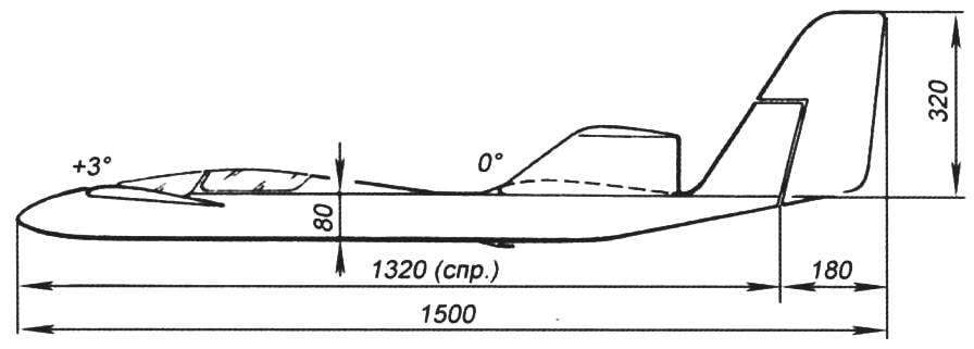
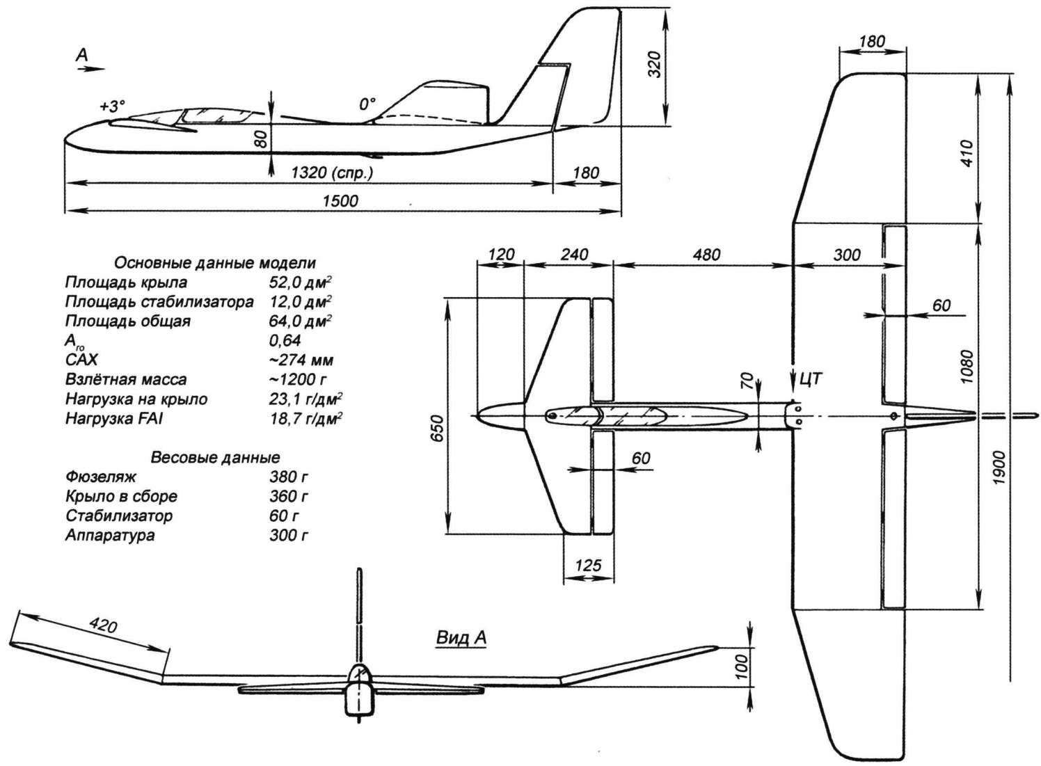
What represents a new model? About external advantages, it is easy to judge by the figure of a General view. Wing relatively small elongation has a straight center section carrying the ailerons, and set at a slight angle the lugs without mechanization. Wing chord chosen is very significant. In addition to increasing the bearing area under the moderate scale of the model, it provides a noticeable increase in the Reynolds number at which the flow around the wing. Hence, the characteristic profile (the coefficients of lift and resistance) will have a better winning ratio compared to the narrow wings. Since initially, the new glider was calculated for flight conditions at low speeds with reduced unit load, the influence of the Reynolds numbers here to neglect it. In addition, with such large chords of the wing can be replaced in a simplified, very high-tech profile (by the way, proved in his time at the same time models). Stabilizer the same profile and a small elongation set according to the height level of the wing. The keel to increase its effectiveness made almost entirely over the wing.
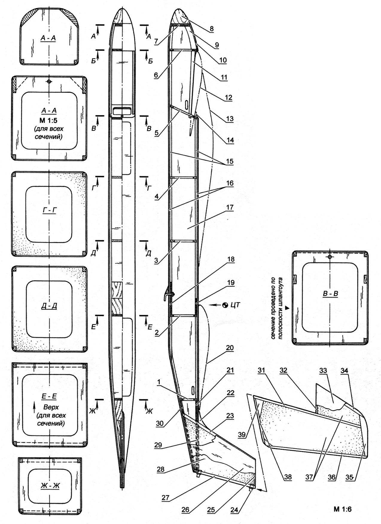
The fuselage and vertical tail:
1 – plywood, s3; 2 — plywood, s3, 3 — s4 PVC foam; 4 – s4 PVC foam; 5 – plywood, s1,2 in three layers; 6 – plywood, s3; 7 – plywood s5; 8 – lime; 9 – Linden (profile); 10 – plywood, s1, 2; 11 – a Linden or aspen s3; 12 – the outline of the stabilizer; 13 – circuit of the lamp; 14 – metal area; 15 – pine 3×4; 16 – plywood, s1,2 with the transverse direction of the fibers of the shirt; 17 – plywood, s1,2 with the longitudinal direction of the fibers of a shirt; 18 – plywood, s3; 19 – plywood, s3; the 20 contour of the wing; 21 – plywood, s3; 22 – lime tree; a 23 – pine 6×8; 24 – the standard loop; 25 – lime 3×6; 26 – plywood, s1,2 epoxy resin; 27 – pine 6×6; 28 – foam PVC s6; 29 – plywood or aspen s3; 30 – plywood or aspen s3; 31 – pine 5×8; 32 – lime 3×8; 33 – Whatman; 34 – lime 8×8; 35 – Linden s8; 36 – lime 3×5; 37 – packing foam; 38 – lip; 39 – Linden s8.
The inside of the fuselage in the parts 14, 18,19 and 21 to put the M3 fungi.
When talking about the aerodynamic configuration is useful to note that even at the design stage there were minor concerns about the stability of the glider to stall into a spin. The fact that antidoping measures at the “ducks” they apply high elongation prednisalone stabilizers, not with sweep of the leading edge. In the derivation of the model at supercritical angles of attack the flow around the stabilizer, initially set at a greater angle of attack than the wing, breaks down earlier than on the wing. As a result, the “duck” due to the loss of lifting force on the stabilizer then lowers the nose down and begins the descent speed, do not showing the trends of entrance into a tailspin. However, all fears, in the end, were in vain. What a spin on a RC glider thing unrealistic, or the overall layout still turned out good, unexpected spin on this model does not occur in any situation. Perhaps there is benefit is expressed as a negative twist of the end sections of the raised “ears”, which, of course, necessary to enhance the aerodynamic qualities of the entire wing.
And if you expect properties and ability to feel updrafts of thermals new technique is comparable to a very good specialized gliders class F3J. By the way, for competition in this class of model can be recommended without any exaggeration (note, perhaps, its relative slow-moving). However, if necessary, to specific conditions of competition for more than a fast car glider loads in addition to center of gravity of the lead bars. The overall quality of planning remains persistently high, and even beginning to affect the grown value of the Reynolds number. As a result, with increasing horizontal speed, the rate of decline is almost unchanged.
Handling the glider “duck” is a little different from the usual models close class. By the way, without regard to the singularity of the General aerodynamic layout, it should be noted that the “aircraft” control (basically only involves the ailerons and the Elevator) after adjustment seems to be more convenient and efficient than a “glider” (rudder and Elevator).
Some modelers may seem greatly inflated the relative areas of all control surfaces. Here it is pertinent to mention that small they can be, but then you’ll have problems with failures of threads on deflected surfaces, will deteriorate handling and aerodynamic quality. But too much rudder, in fact, is simply not the case. Does not introduce any problems of arbitrarily large ratio rudders and fixed aerodynamic surfaces. As this view is at odds with the generally accepted amongst modellers-“practitioners” theory, this question need more detail. So…
The common opinion is based on incorrect logic, when the area of the rudders is associated with the degree of controllability of the model. In fact to get on any plane or glider is absolutely whatever the degree of “natoplennoy” even if the all-moving stabilizers! The only factor that really affects handling, is the angle of deflection or of the same all-moving stabilizer. Is to use hog a great height, and you eventually will be faced with insufficient controllability even when the huge rudders! It should be noted that the reduction of deflection angles to achieve better due to the size of hogs. Attempt to go on the shorter shoulders of the levers wheel machines will provide the desired effect, but will lead to the growth of the influence of backlash in the whole scheme of the drive wheel. And the backlash is always bad, but not so for the large rudders. The latter are good because they usually tougher small and narrow, always sufficient for all requirements of control and, in addition, due to small angle deviations introduce minor additive to the aerodynamic resistance in the rejected state.
Anyone who has even a passing familiarity with the theory and practice of calculating the hinge points of the rudder, may try to argue that large wheels will require increased effort in the steering wheel-cars. It really would be so, if not to take into account the peculiar degree of reduction in the transmission in the control system. Increased hog cause not only decrease of deviation angles of the rudder, but also a corresponding increase of control points on the rudders. So in this sense, all, in the end, it turns out, at least not worse than in compliance with (execution) of conventional proportions.
Of course, in a conversation about the manageability should never be confused with the stability of the model. Stability is ensured by their design techniques and balancing of the model. And she can not be related to the relative area of the rudders. And finally the topics of controllability, we note that the above applies not only to models of non-traditional schemes, but also, and primarily, to all conventional motor models and gliders.
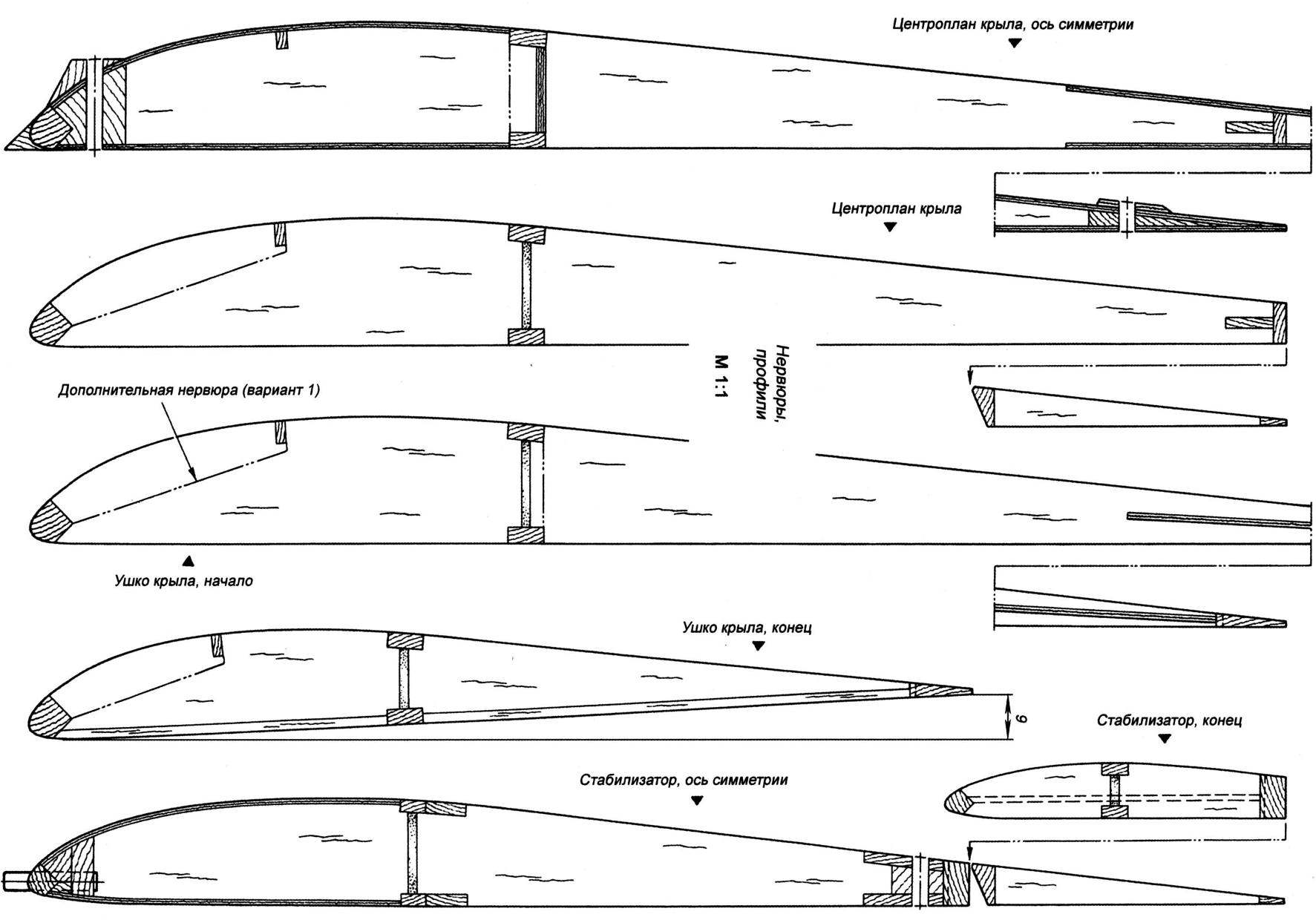
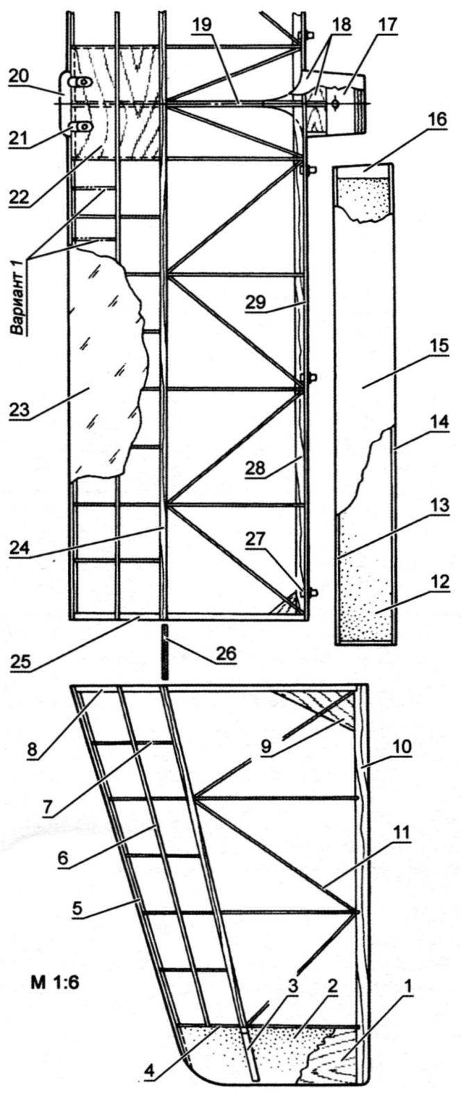
The center section, the lug and the wing Aileron:
1 – aspen s2; 2 – foam stamps PVC; 3, lime; 4 – aspen s2; 5 – pine 6×7; 6 – pine 2×4; 7 – aspen s2; 8 – aspen s6; 9 – plywood s1,5; 10 – pine 3×13; 11 aspen, co s2; 12 – light foam; 13-aspen 4×8; 14 aspen 2×5; 15-Whatman; 16-Linden; 17-birch; 18 – plywood, s1,2; 19 – aspen 5; 20 – lime; 21 beech; 22 – plywood, s1,2; 23 – Mylar or proprietary thermoplastic Mono-Cote; 24 – grained pine 3×7; 25 – aspen 6; 26 – switching of three layers of plywood 1; 27 – the standard loop; 28 – pine 2×10; 29 – pine 2,5×8
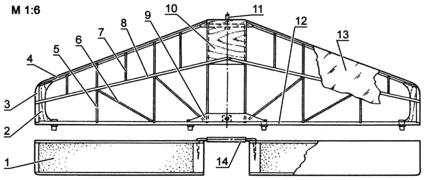
Stabilizer and Elevator:
1 – melkosortnyj foam; 2 – plywood s1,5 ; 3 – Linden s4; 4 – pine 5×5; 5 – aspen s2; 6 – aspen 2; 7 – aspen s2; 8 – pine 2,5×5; 9 aspen, co s2; 10 – plywood s1 ; 11-beech Ø4; 12-сосна5х8; 13-Mylar film or Mono-Cote; 14 – steel Ø2. 5 in a brass tube.
Design handlebars similar to ailerons
As for the airframe, I hope that a special explanation she does not need – everything is clear from the drawings.
Striking the fuselage under the scheme easier to any other. It can be assembled first in the form of a frame, followed by covering with plywood or panels (plywood panels with mounted on them stringers), which later with the help of frames are collected into a single product.
The constructive scheme of the wing with diagonal half ribs provides not only strength, but also increased rigidity of the wing torsion, which is necessary when you use a soft skin. The only thing you need to pay attention to is the pronounced negative twist tabs that must be set during Assembly using wedge-shaped rails placed under the trailing edge of the frames. The fact that the diagonal polonaruwa give the wing rigidity is such that to set the required twist flat lugs then simply will not succeed.
In principle, piecemeal, the proposed airframe is simple, and at desire it is easy to reconstruct a building from balsa. However, in this case it can be justified only when pereprofilirovanie wing. If you can reproduce the design without radical changes, the only thing that will give the use of balsa is some reduction in the mass of the model. And this glider is so easy to use.
Note apparent initially unjustified strengthening of the keel. So different from the General power circuit design of the keel was not due to balancing issues (the duck weight balance is achieved in a wide range of transfer elements side of the radio from pastabilities section of the fuselage in the wing and Vice versa). The strength of the keel provides for the possibility of subsequent installation of the nacelle with the engine working volume of 2.5 cm3. Referred to miss a promising opportunity not like, and the keel was pre-hardened. What happens as a result of the motorization of such a glider, you can easily imagine it would be an easy plane, and having a tricycle landing gear with nose wheel and fairing on wheels. Try to at least mentally glider complement these details – and you will see that the overall design of the model will benefit.
K. SHUMEEV, master of sports
Recommend to read
 “Vyatich” motor-cultivator
...The silence of a sunny spring morning was shattered by the sharp clatter of an engine. A peasant digging his garden with a shovel straightened up and looked over the fence at the... WITCHED
Skis kept slipping off... Leaning on a stick, he made a hesitant step forward, but only tried to pull foot slipped, and I had to start all over again. I waved to him, and, intending to...
