RC INHERITS “THE OLD DAYS”

RC INHERITS Now all over the world modelistica there is a clear trend of withdrawal from the limited rules of the canons of sports equipment. Appear constantly and steadily there are model subclasses: for example, microplane, or, conversely, models of the giants; in several countries, along with other, an official Championships held with the technique created by drawing almost half a century ago.

Will try to keep up with fashion we. If micro – or Maxi-planes require virtually inaccessible for the average Modeler equipment and engines, we work in the style of “retro” we would succeed. And following this direction, as it turns out, can give very interesting results.
 
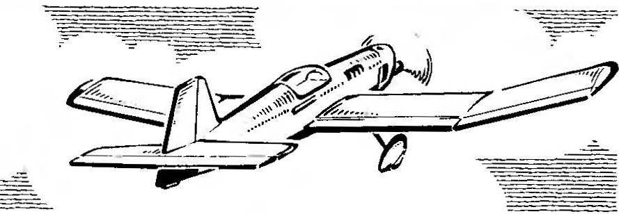
We present radiomodulators the machine is designed under the obvious influence of the mass at the time of the expense of building a traditional class of motor vehicles. They were characterized by wings with a double “V”, a rather large shoulders of the horizontal tail and unthinkable from a modern point of view, plus size area of the stabilizers. Also typical was the design and techniques used in the solution of the power circuit.
 
What is the result of the translation of the “rarity” of the design practices on current conditions radio-controlled technology, can be clearly seen from the drawings. Since the construction of this model is based on the well-known in the mass modeling techniques, it is possible to just require a special explanation.
 
First of all, about the total aerodynamic scheme. To us it seemed very fertile, as it provides good characteristics of stability and controllability of the corresponding decrease of the angle of the “V” of the wing and the square of the stabilizer. In addition, due to the small spacing according to the height of the axis of the propeller thrust, wing and stabilizer you can count on the small effect of wind and air gusts. RC in the proposed design not only has a low specific loading on bearing surfaces (which is more than important!), but also allows us to achieve extraordinary versatility. The fact that the replacement of the engine hood on the cowling, the power supply apparatus of the engine of the plane is a glider. Flexibility in any application of the model improved by moving to the land of powerful flaps. Lowering them by 5° — 7°, in conditions close to the wind, can be achieved simultaneously using an airscrew of larger diameter and a reduced step, unthinkable though slow and steady flight. The glider in this form on the flight speed and reduce a little behind the championship class models A21 If desired, the flaps can, on the contrary, raise of 2°-4°, thus obtaining more high-speed, insensitive to wind and similar in characteristics to a good pilotagem car.
Power circuit of the new model is simple. Noteworthy technology building wing, or rather the manufacture of a number of accurate and robust ribs. They formed two polutorki, pre-shaped mandrel in a broad band from millimeter three layers of veneer, which is then carefully sawn into individual elements of the desired width. If you are not too concerned about the timing of the creation of the model can be applied to the wall finished and the shelves separately. Centroplane and “lug” frame elements collected separately and joined after complete Assembly. The flaps and ailerons seem at first glance somewhat complicated, in fact, in the work of Assembly is very simple. The fact that their plywood front wall glued only at the very end, and before the process of assembling individual slats (they, these braces may not even be sized by length as the front of the ailerons and flaps could easily be cleaned before installing the plywood wall). But, having finished the wing mechanization, is very light and udivitelno rigid in torsion, you will be rewarded for “jewelry” work.
 
Fig. 1. The main geometric parameters of the model (in brackets are the increased size modifications, designed to fit the engine displacement to 6.5 cm3).
 
Fig. 1. The main geometric parameters of the model (in brackets are the increased size modifications, designed to fit the engine displacement to 6.5 cm3).
 
 
R and p. 2. The fuselage
 
R and S. 2. Fuselage:
1 — spinner (the cap from a bottle of shampoo), 2 — modified engine KMD-2,5 with rear wall from “Rhythm”, 3 — the hood (the hood of the s sheet aluminum, Plexiglas or dugout detail of lime), 4 — container tank (paper in epoxy resin in three to five layers). 5 — top stringer (pine W X 3 mm), 6 — fuel tank (bottle made of polyethylene with a volume of approximately 80-100 cm3), 7 sheathing (plywood or 1 mm cardboard thickness 0.3— 0.4 mm in two layers), 8 — stringer amplification window of the aisle “language” pine (3X4 mm), 9 — a lateral stringer (4X4 mm pine or spruce a light 5×5 mm), 10 — talsano (plywood 1 mm) 11 — light (plexiglass thickness 0.8—1.2 mm), 12 — details of framing and polycarbonate cabin (Linden and veneer), 13 — upper fairing (lime 30X 10 mm; after adjustment of the place caving to wall thickness about 2.5 mm), 14 — inclined bulkhead (plywood 1 mm), 15 — stringer (pine SX 5 mm) 16 — the leading edge of the keel (pine or basswood with a thickness of 5 mm), 17— parts of a set of keel (Linden 5 mm thick), 18 — trailing edge (pine 5X X5 mm) 19 — boss frame (plywood 3 mm), 20 — Klondike (Linden 3 mm), 21 — the cradle of the stabilizer

 
Fig. 3. Wing
 
Fig. 3. Wing:
1 — ending (plywood 2-3 mm), 2 — front flange (lime 7ХІ5 mm; after pre-profiling to facilitate the gouging to the wall thickness about 2.5 mm; at the junction of ribs with shelves under them to saw through the slots to a depth of 2 mm), 3 — reinforced rib (same model, but have a full foam wall thickness of 2 mm), 4 — spout (similar to the standard ribs), 5 — typical rib (see Fig. 4), 6 — stringer, 7 — the node of the rocking actuator Aileron, 8 — lining the shelves of the spar (plywood 1.5 mm). 9 — strengthening of the root zones of spar (1.5 mm plywood with a wrapping of cotton thread with glue), 10 — double sided sheathing of the root zone (plywood or cardboard), II — the root rib (two plates of plywood pasted with 1 mm in between the frame rails, the total thickness okolo7 mm) ,12 — boss under the pin fixing the console 13 — Klondike (Linden 3 mm), 14 — trailing edge spar Assembly (see Fig. 4), 15 — adjustable flap, adjustable on the ground before the flight, 16 — node interface of the rear edge of the spar, 17 — slip scarf for the passage of thrust Aileron (1 mm plywood), 18 — Aileron Assembly (see Fig. 4), 19 — ending of spar (Linden 5 mm).

 
R and p. 4. Pattern typical rib of the wing
 
R and S. 4. The template model of wing rib:
1 — front edge (see Fig. 3), 2 — flange ribs (I glued on a mandrel in epoxy resin three pine steamed or * fake plates with a thickness of 1 mm; workpiece after curing, the first resin is cut into slats with a width of 4 mm), 3 — stringer (pine 3X5 mm; at the junction with the ribs made the cuts with a depth of 3 mm). 4 — filler (foam PS-4-40 or PVC thickness of 5 mm), 5 — beam flange (tight runolinna pine 5X 5 mm), 6 — Klondike solitaire (plywood 2 mm), 7 — shelf rear spar (pine 2X5 mm) 8 — wall (plywood 1 mm), 9 — plate spar of the flap or Aileron (Linden 2X 11 mm), 10 — M braces (pine 2X2 mm), 11 — trailing edge (pine SX 6mm) 12 — wall (plywood 1 mm).


R and p. 5.
 
R and S. 5. The “language” of wing mounting:
1 — Central insert (plywood 5-6 mm), 2 — through socket for stud fixing consoles wing, 3 — lower the power panel (plywood 2 mm), 4 — the outline of the fuselage, 5 — upper power panel (plywood 2 mm).


Fig. 6. Stabilizer
Fig. 6. Stabilizer:
1 — boss (Linden 4 mm), 2 — sided paneling of the Central zone (1 mm plywood), 3 — spacer rib (pine 2X4 mm), 4 — rib (pine 2 X6 mm), 5 — force front edge pine (6X18 mm; ribs punch in the edge to 2 mm), 6 — ending (Linden 6 mm), 7 — loop swivel suspension steering, 8 — trailing edge (pine 2X6 mm), 9 — wall edges (pine 2X6 mm) 10 — Elevator 11 — back boss (Linden 4 mm).


Seemed interesting to us and language suspension of the wing, characteristic of the old models. If you correctly calculate the strength of the connecting language,… will be able to not only sufficiently rigid connection, but in practice a robust wing. After all, undeservedly forgotten language mount the consoles so well that provides the easiest Assembly of a wing model in all directions off-design loads. From slipping consoles with languages protects the wood stud, and at the same time passing through the root of the wing. Do the studs from the durable material, there is no need: in flight, they are not loaded, and when an unplanned encounters models of the earth, these items must srazhatsya without any effort. Stabilizer to improve remotecodebase and for the convenience of working on the elements RC is designed not shear, but removable.
 
In conclusion, I would like to note that the proposed model, in addition to a wide versatility, thanks to the good flight properties can be created and increased. As regards the number of power components, while maintaining the main power circuit can achieve only a small increase in the mass even if the wingspan is 1870 mm. With a weight up to 1500 g for steady flight with a small number of aerobatic figures, including the upward sections, quite a good engine working volume of 2.5 cm3.
 
V. TIKHOMIROV, master of sports

Recommend to read

  • THE INVISIBLE WATCHMANTHE INVISIBLE WATCHMAN
    Generators of low frequency oscillations, as is known, can be used as a caretaker: intermittent loud noises warn of the approach of a stranger. On the same principle and made our...
  • HEADSETS FOR ATTICHEADSETS FOR ATTIC
    "In one of the rooms of the journal among the tips I was interested in the original triangular door leading to the attic. We have not solved the problem of the use of the space under the...