
 Master of sport international class, world record holder Vladimir Malinkin today recognized as the leader of korovikov, speakers with high-speed models.
 Although Volodya was fascinated by model airplanes during his school years, to the sport he came quite late, but quite Mature and accomplished designer and athlete. In 1973, Maslenkin became the master of sports of the USSR, three times headed the tournament table of the championship of the USSR on speed cordovil, won in international competitions in Poland, Bulgaria and the Soviet Union. Model maslenkina distinguished by the boldness of the solutions, the finest engineering design and excellent finishing. No wonder they attract attention at any event. In collaboration with Stanislav by Zhidkova Vladimir first in the country created the original cord model the so-called asymmetric schemes. Innovative design Moscow modelers largely contributed to a sharp increase in velocity models of this class.
The model consists of low spar, cowl of the fuselage and detachable wing. Low cut on a lathe from magnesium alloy MA 8-MA12 and milled so that the tabs of the engine is not performed for an axis of the connector, located 5 mm above the axis is low. A spar of the same alloy attached to the inside low four countersunk screws (you can use argon arc welding). In the groove in the rear part is low on glue K-153 mounted plug, the end surface of the fixed two wire pins. Into the groove and glued the tail pylon.
Installed in the spar rocking chair from a sheet of alloy D16T. It establishes the control cable Ø 0.7—0.8 mm, which put Bowden wound wire OVS Ø 0,25—0,3, the Ends of the Bowden glued to the inside of the plane is low and the pylon. The hood of the fuselage, stacked, has a power rack — hornbeam and lime — glued them to the balsa block. Seven fungi were planted in a frame on the glue, securely connect the low with the hood. Stabilizer — balsa, reinforced with lime trim and spar. Installation angle of 0°. Thickness in the mid-4.5 mm, at the end of the 2 mm Profile is symmetrical. On the hood there is a small continuation of the wing at an angle of 1.5°, insuring the model from collapsing when stopping the engine.
The wing is a sheet of alloy D16T. Profile — concave, symmetric, the relative thickness of 7%.
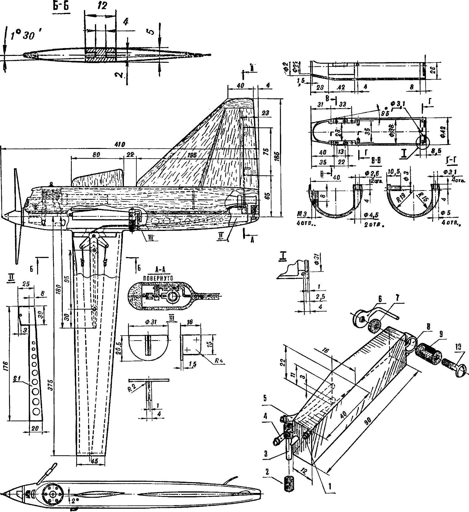
Fig. 1. The fuel tank and its elements:
1 — tube gas, 2 — rubber tube, 3 — bracket, 4 — tube power supply, 5 — drain pipe, 6 — spargana, 7 — sleeve (Ø=9, l=3), 8 — Cup, 9 — sleeve (Ø=9, l=23), 10 — a tightening screw.
The technology of manufacturing of the wing presents no special difficulties. For flexible workpieces it is convenient to use a simple fixture. It’s two boards of size 500Х120Х250 mm, well-matched to each other and connected by four hinges-hinges (Fig. 2). Plywood thickness 10 mm make the mandrel (Fig. 3) height is greater than the chord of the wing, obstrusive one of its sides into a cone shape resembling an airfoil.
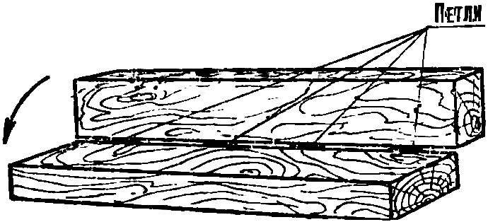
Fig. 2. Device for a flexible wing.
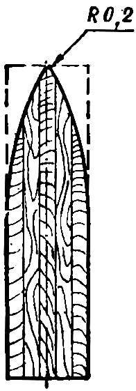
Fig. 3. Mandrel.
Then between the two halves of the billet lay the wing so that the axis of the latter was at the edge (Fig. 4). This operation must be done together: one holds the workpiece, the other of the mandrel bends the sheet at a right angle, and then, laying in the fixture, together push him to the corner of 15-20° (Fig. 5).
To get the right radius on the front edge, the workpiece attaching a strip of plywood with a thickness of 1 mm and dormice until it stops (Fig. 6). You will get an inner radius of 0.5 mm. to Reduce it is impossible, as the edge begins to crack.
Bezel pry the workpiece (Fig. 7), cut to the desired size and glue trailing edge (best to use adhesive PU-2). After drying, the front and rear edges: glue the spars and the wing end — the fake boss with holes for cords.
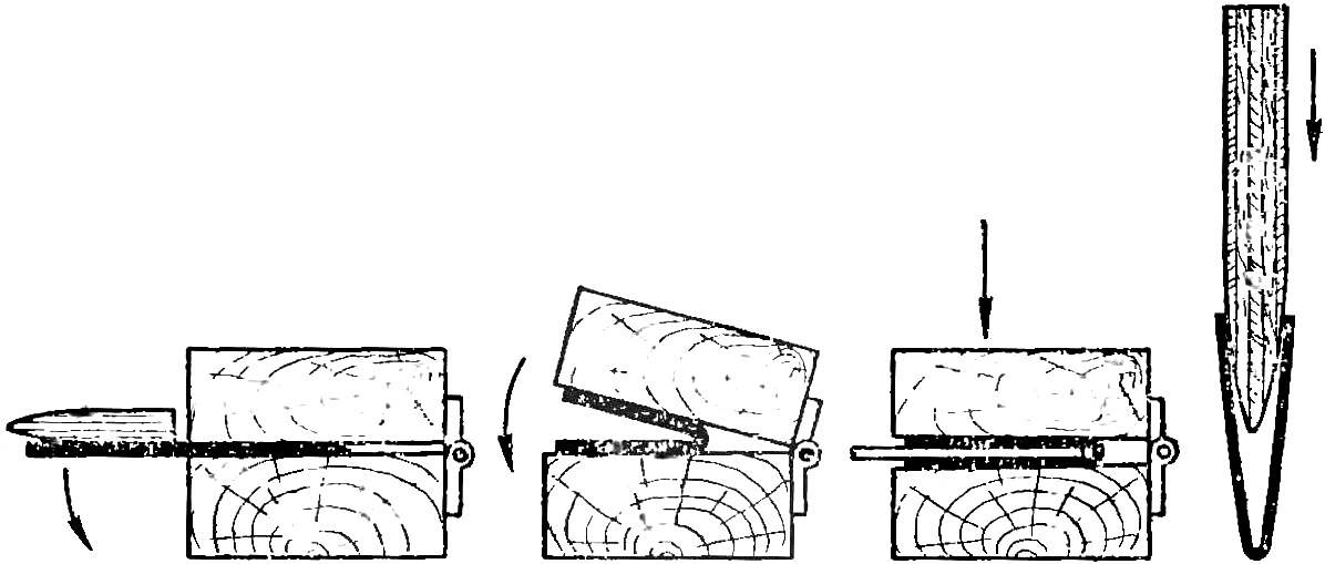
Fig. 4, 5, 6, 7. The bending process of the workpiece of the wing.
Low cowl with sand paper and apply one layer of fiberglass with epoxy.
In the nose of the hood cut out under the window diffuser and engine cooling. Glue the landing ski of the wire OVS Ø 2,3 and the end solder the amplifier of carbide metal. This design will allow you to make many flights without replacing the skis.
Additionally, the front hood glue fiberglass with a thickness of 0.05 mm and finally etch the surface with sandpaper.
Model coat of polyurethane paint and Polish. Tank (Fig. 1) made of tin with a thickness of 0.3 mm hang on the rubber cambric on low. Insert the air intake, connecting it to an elastic rubber tube with a drainage tube of the tank.
It is time to install the wing and insights cords. To do this, assemble the model completely and hang it over the cord (steering wheel in neutral position). To compensate for the deflection of the cords while in flight, select a wing position in which the nose of the model will descend 2-3 mm below the horizon (Fig. 8). Then drill the holes for the wing mounts.
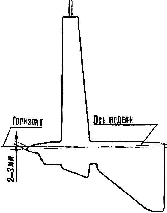
Fig. 8. Installation of the wing (hanging).
The next stage includes the manufacture and preparation of the bolts and starting of the truck. The latter should be relatively easy, reliable. It is equipped with two grips which hold the “sword” and are released when lifting the model together with the truck at a height of 20 cm ensures a secure take-off and eliminates breakage of the screw.
Propeller: two-blade — Ø 150 mm, pitch 165 mm; single blade — Ø 176 mm, 190 mm When using the latter be careful since breaking it during the flight leads to complete destruction of the whole structure.
Debugging models is usually carried out on the engine with a very weak pair, the length of the pipe it is desirable to have not less than 315 mm (from the axis of the cylinder to the pipe end). Tank put on the enrichment, and the engine output to almost maximum speed. This mode provides a quick and safe take-off.
In a well-functioning tank, the speed of the model should not change throughout the flight (25-30 laps). This configuration allows the assistants to measure the speed and send a signal to the athlete. If the speed is unsatisfactory, you can turn the engine off forced stop, and after an adjustment, try again. All this makes it possible for one to attempt to produce up to 6 UPS, which contributes to the achievement of high results.
V. MASLENKIN, champion of the USSR, master of sports of international class
Recommend to read
 Roller Scooter
It seems incredible that the chrome-plated roller bike, one of the numerous exhibits at the Central Exhibition NTTM-82, was made by teenagers — it has a very "factory-made" appearance. And...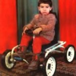 CHILDREN’S RECUMBENT
I'm a longtime subscriber of the journal "modelist-Konstruktor" — since 1968. However in the past two years, wrote out "Technique—youth", but now once again gave preference to your...
