
 Lately in the aviation modeling widespread flying models, radio controlled, including helicopters. For the first time such a model was demonstrated in 1959 at the all-Union competition of S. Vorobyov. To control the flight he applied the principle of changing the alignment of the apparatus. After a year in the championship, in the background, a helicopter appeared Borisov with an aerodynamic rotor drive. In 1964, at a match meeting of the athletes of Moscow and Leningrad, he introduced the concept of B. Yuriev new model with tail rotor. However, the car was “raw” and, unfortunately, remained unfinished.
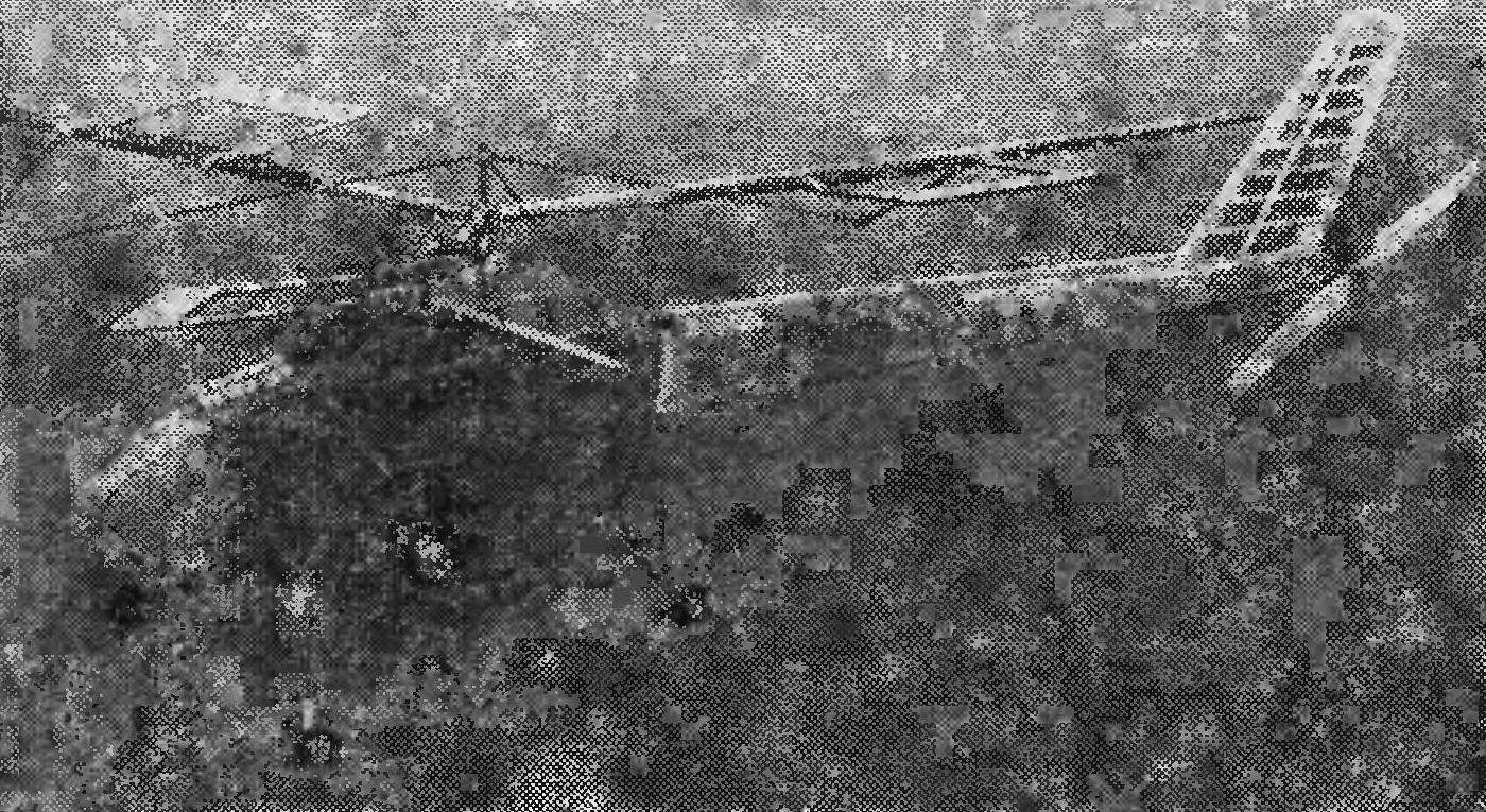
For a number of years and the author of the article V. of the Casts worked to create a radio-controlled model helicopter. In 1977 she was built and made several successful flights with a duration of several minutes, despite the relatively low power of the engine.
Famous foreign models of helicopters, usually heavy, because they have complex control system — hence the need for powerful (up to 10 cm3) engine. The advantage of a model Slepkova in its simplicity. It can perform controlled turns, despite the limited number of teams, and has the engine 2.5 cm3.
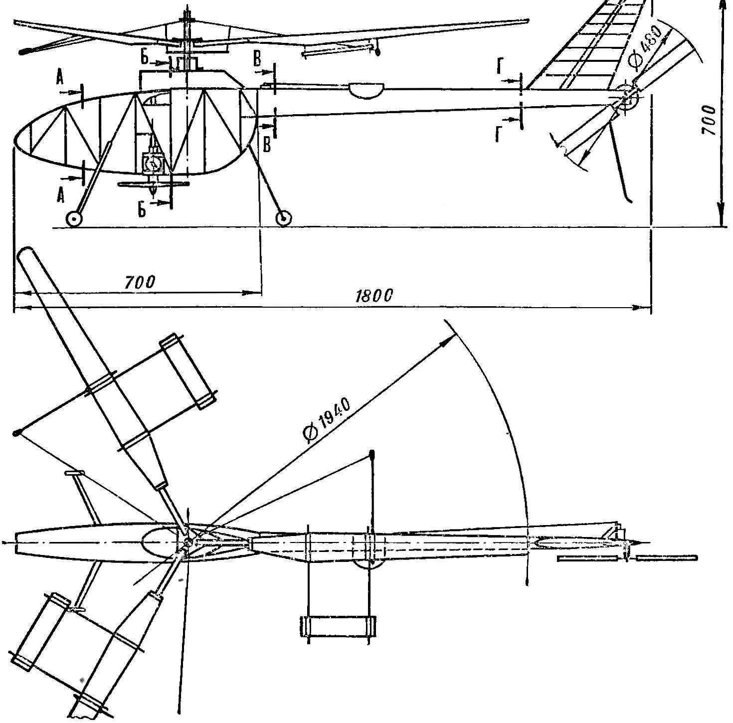
Fig. 1. Diagram of the helicopter model.
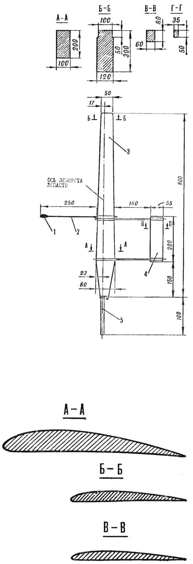
Fig. 2. The blade of the screw:
1 — stabilizing cargo, 2 — lever, 3 — blade, 4 stabilizers, 5 — Bush.
The model is available to a wide range of model aircraft.
THE CALCULATION OF THE PROPELLER THRUST. Building any model starts with the selection of key parameters and definition of engine power. You can then go to the definition of propeller thrust. According to the formula N. Ye for hovering it is calculated as follows:
T = (33,25 • N • D • η0)2/3,
where N is engine power in HP;
D — diameter of propeller in metres; and η0 is the relative efficiency of the rotor.
Less losses (40%) on the rotation of the tail rotor, fan and gearbox engine power for operation, the rotor is 0.15 HP
The value is relative to the efficiency of the latter can reach 0.7—0.75, and given the deterioration of the aerodynamics of the screw for stabilizing cargo and stabilizer — 0,6.
Substituting these parameters into the formula defined by the thrust:
T = (33,25 • 0,15 • 1,94 • 0,6)2/3 = 3,3 kg.
However, during horizontal flight, it may rise from the reduction in induced drag. This is confirmed by flight tests. With the engine set to max power, climb rate model reaches 1-1. 5 m/s During throttling of engine, the model makes a horizontal flight.
The rotor model consists of three blades. Each of them (Fig. 2) can be rotated in the sleeve about an axis passing through the line of the foci, that is, has an axial joint. The installation of angle of attack in flight takes place automatically via a stabilizing load that the rod (nylon fishing line Ø 0.5 mm) connected to the shaft. At low rotation of the rotor stabilising the load is lowered and thus reduces the installation angle of the blade, aligning the rotary speed.
When the deviation of the plane of the rotor and they cyclically change the installation angles of the blades and return the rotor to its original position. For damping relative to the hinge axis it is equipped with stabilizers, which, moreover, improve the transition model in autorotation.
The profile of the blade is convex-concave, variable — thickness and concavity decreases to an end. In the most wide place (section a — a) relative thickness is 12%, the concavity — 6%. In the end, these values are respectively 8% and 4% (section b — B).
The blade is made of balsa, the front and rear edges of pine. Axis steel Ø 5 mm, glued in resin and fixed steel pin Ø 2 mm. and it Rotates in the sleeve on two ball bearings of the type 1000065 (outer diameter, 13 mm). The blades can be rotated in the range of — 5° and + 40°.
The profile of the stabilizer PLANO-convex, with a relative thickness of 8% (section b — b), made entirely of balsa specific gravity 0.1 g/cm3. As blade, he macalintal covered with paper, painted and coated with nitro on top of the polymerized varnish. For level flight the model includes a swashplate (Fig. 3), cyclically changing the installation angle of the blade relative to the fuselage.
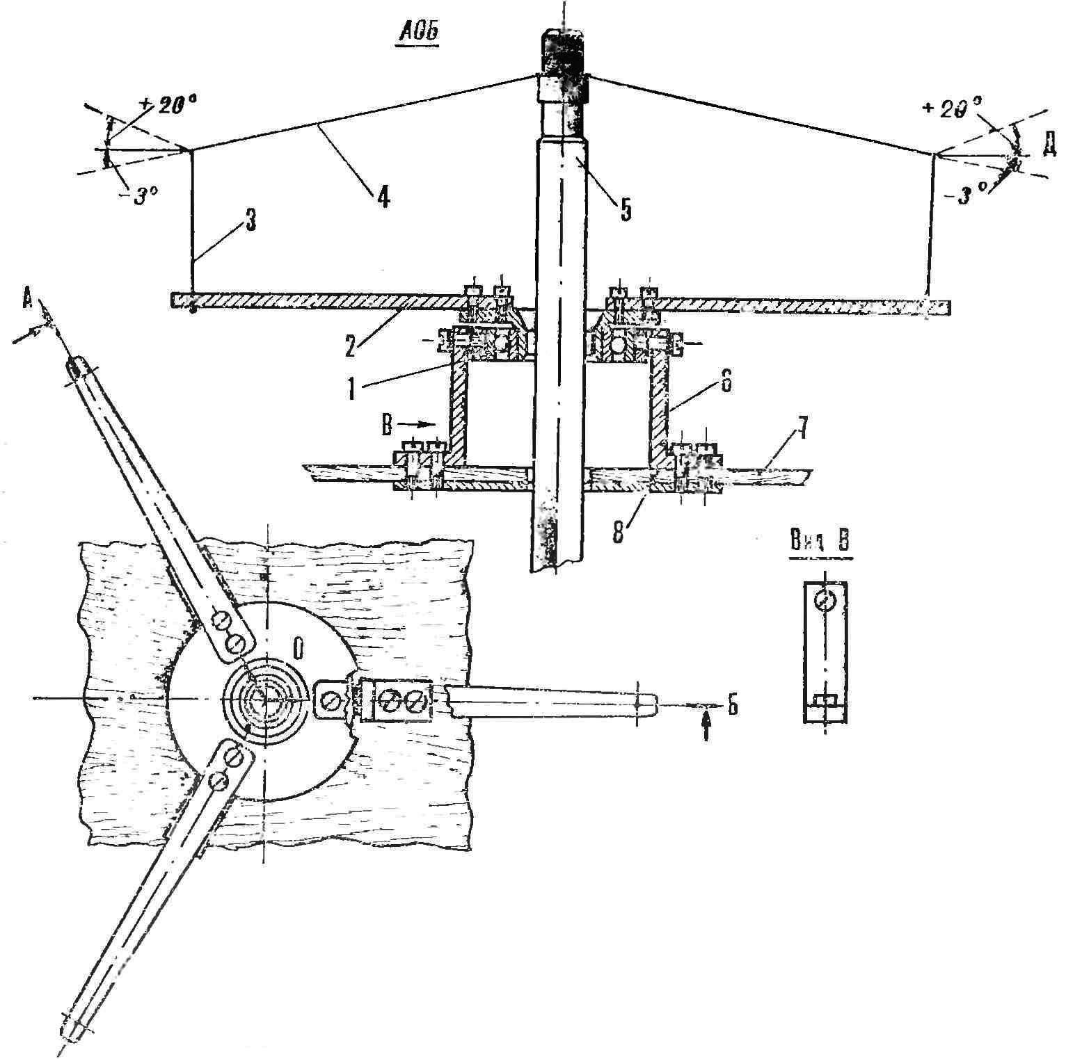
Fig. 3. Swash:
1 — bearing, 2 — lever, 3 — the managing pull, 4 — pull to stabilizing load, 5 — shaft bearing vitp, 6 — stand, 7 — gear-housing, 8 — place setting shims to adjust the plane of the swashplate (within 0-10°), D is the range of angles rods, going to gruzinam stabilizing during flight.
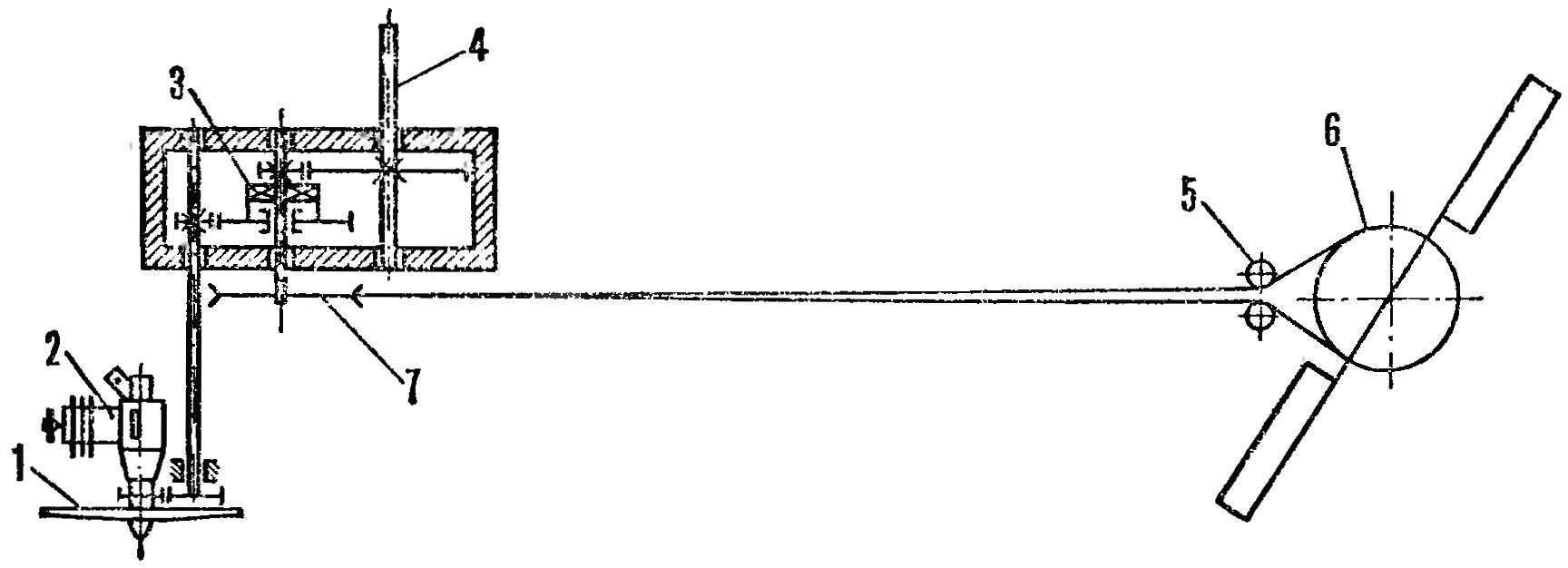
Fig. 4. Kinematic scheme of reducer:
1 — motor, 2 — flywheel-fan, 3 — clutch, 4 — shaft rotor 5 guide roller, 6 — clutch pulley 7 — drive pulley.
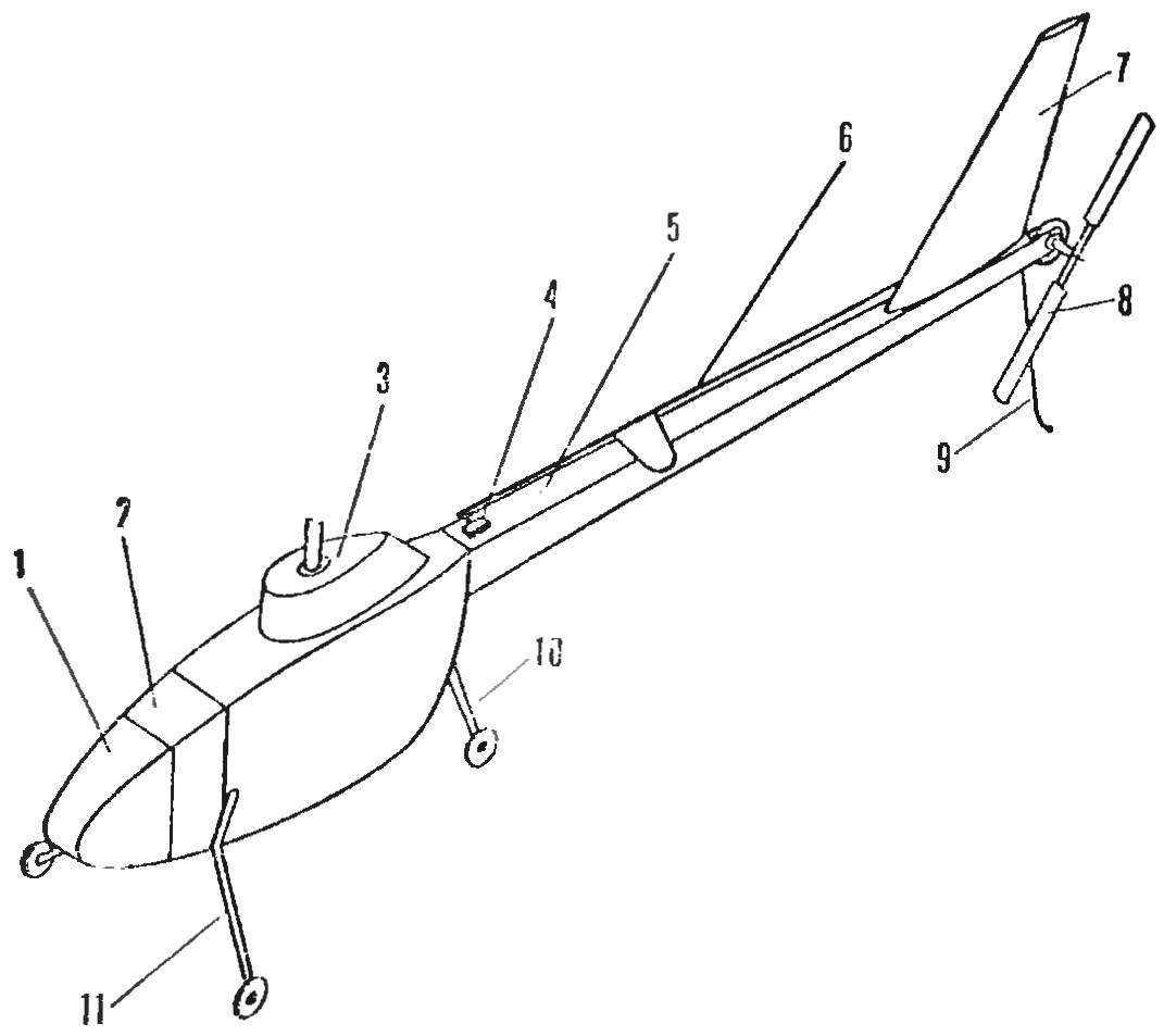
Fig. 5. Layout of the fuselage:
1 — Central part, 2 — compartment, for radio, 3 — gear-housing, 4 — servo 5 — tail beam, 6 — control rod, 7 — Kiel, 8 — tail rotor, 9 — spike, 10 — rear stoick chassis, 11 — nose landing gear.
In the considered model, this angle is fixed, is adjusted to a constant horizontal airspeed of V = 5 m/s.
The design of the swashplate bearing is based on the Tina 1000903 with internal Ø 17 mm and max 30 mm. Outer ring of a bearing attached to the fuselage at three dural racks installed at an angle of 10° to the plane of rotation of the rotor in the course of the flight. With the rotor rotating and the inner ring with three arms that are connected with stabilizing rods goods which cyclically change the pitch of the blades.
The tail rotor has two blades (Fig. 1), rectangular in plan, a width of 38 mm. the Profile is convex-concave, the thickness of the butt of 12% at the end of the 8%.
The helicopter is controlled by the rate of change of the screw pitch. The average value of the angle of the blades is 15°, the range of variation of their angle of rotation — 2° + 12°.
THE ENGINE AND GEARBOX. A model engine with a cooling jacket Ø 40 mm mounted at the bottom of the fuselage with parts cut out of aluminum. On its shaft is mounted a first gear reducer (Fig. 4) and a fan.
Rotor gearbox is three — stage. The first step performed on gears with a module of 0.5 mm width and 6 mm main steel with number of teeth Z1 = 37, led by the brass with the number of teeth Z2 = 48. The second step has a gear with a module of 0.6 mm lead — steel, led — dural, respectively, number of teeth Z3 = 23, and Z4 = 177. The third stage — in the gears of the same material as the second. Module is increased to 0,8 mm, number of teeth Z5 = 20, Z6 = 100.
Thus, the total gear ratio to each other shafts of the engine and the rotor will be:
I = Z1/Z2 · Z3/Z4 · Z5/Z6 ≈ 1/32 .
The rotation of the main gear to tail rotor is passed through the annular nylon thread and two pulleys, machined duralumin. Leading installed on the second stage gear, driven — steering screw. Their diameters are the same. Because the last stage of the gear has a gear ratio of 1:5, then without slipping the tail rotor rotates five times faster than.
In the second stage of the main gear set freewheel, ensure that the descent of the helicopter when the engine stops. Autorotation does not violate the connection between the main and tail rotor that allows you to control the rate model at lower.
During the tests both on the ground and in flight motor with gear worked for about three hours. In this case I needed to replace the piston and ball bearings of the motor shaft. Wear of the gear unit are not exceeded the permissible value.
The FUSELAGE consists of two separable elements: the Central part and the tail boom (Fig. 5), which are connected by rubber threads. This mount securely holds the tail boom in flight, and relieves the load upon impact on landing. Design recruited from the pine stringers with a cross section of 3X3 mm2 in the tail boom and 5X5 mm2 in the Central part, which has 7 frames from plywood thickness of 1 mm, reinforced with pine slats cross-section of 3.5 X 3.5 mm2. The place of fastening of the engine bottom is reinforced with plywood with a thickness of 5 mm. Reducer its upper portion by screws М4Х10 mm is attached to the side bars of 10X6 mm. cross-section of Its casing is glued together out of balsa wood with a thickness of 2 mm.
All nodes of the fuselage are connected by epoxy resin, which provides sufficient strength and protection from exposure to fuel.
For the placement of receiver and decoder in the front of the fuselage made a special compartment. Front landing gear the curvature of duralumin plates with thickness 2.5 mm, rear — weeding of two steel rods Ø 2.6 mm. the Central part of the fuselage is covered in nylon, the tail boom is macalintal paper.
RUN. The model starts with it. The motor is driven in the usual way, for the flywheel-fan. To facilitate the launch can starter.
First flight should be carried out in calm weather when the neutral position of the ring of the swashplate. Time of engine operation it is desirable to limit timer. With the right start the helicopter climbs vertically at a speed of about 1.5 m/s.
After work the engine model, it goes into autorotation. To prevent rotation of the fuselage lever tail rotor control on the remote control reject to the right.
Further flights can be performed rejected the ring swashplate, so that the helicopter can take off with a horizontal speed and managed on the course.
THE MAIN PARAMETERS OF THE MODEL
The diameter of the rotor, mm — 1940
Omitama surface DM2 — 294
The weight of the model, g — 2950
The fill factor of the rotor — 0,065
The diameter of the tail rotor, mm — 480
In-flight engine power, HP — 0,25
The speed of rotation of the motor shaft in flight, rpm — 12 000
Gear ratio from engine to rotor — 1:32
Gear ratio from engine to tail rotor — 1:6,4
The speed of rotation of the rotor, rpm — 375
The speed of rotation of the tail rotor, rpm — 1875
The weight of the equipment installed on model g — 515
V. IMPRESSIONS, candidate of technical Sciences, master of sports of the USSR
Recommend to read
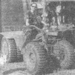 TIRES FOR ATV
After the publication of "imaginative artists of Karelia" in No. 1 of 2008 "Modeller-designer" category "Panorama photos of readers 'letters" to me began to address the readers-homebrew...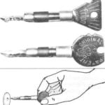 THE KEY LABELED
Clever locks are supplied with a no less intricate keys, which in contrast to the traditional plain old no beard, clearly suggests the correct position of the key when inserting it in...
