Prepared and otmuchivanie frames are bonded with a plasticized epoxy resin (e.g., brand ED-20) side of the balsa plates with a thickness of 2 mm. Fixation of the sidewall — rubber cord, imposed at the locations of the frames. At the junction of the wing to the fuselage side balsa strengthened with plates of plates of the same thickness. After curing of the resin frame is attached to the lower skin of the fuselage is a balsa plate with a thickness of 2 mm. Further from the workpiece carefully removed the staple-core, and glued to the fuselage top covering the rear of the fuselage. When it is necessary to consider that between the first and second frames on the four bolts installed the balsa cover, which houses the fuel tank.
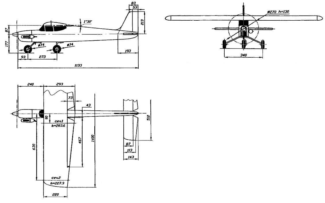
The layout of radio-controlled models “the Coach”:
1 — engine 0.S.MAX-40LA; 2 — engine mount (aluminum); 3 — frame 1 (s5 balsa, reinforced with two sides of 1 mm plywood); 4— fuel tank (plastic vial 100 ml capacity); 5,9,11,13,16 — frames no 2-6 (balsa s5); 6 — servo control Aileron; 7 — servo control carburetor engine; 8 — servo control rudder; 10— steering machine of the Elevator control; 12 — upper covering of rear part of the fuselage (balsa s2); 14— keel (balsa s6); 15— boss (balsa); 17— sheathing the lower part of the fuselage (balsa s2); 18 — support bar spring chassis (beech, 30×15 bar); 19 — screw M5 mounting spring main chassis; of 20.24 — wheel suspension; 21 — the receiver of the control system; 22,23 — M4 screws mount the front landing gear; 25 — a plug of the nose landing gear; 26 — the hood (AMG, sheet s0,5); 27— wing; 28— the sides of the fuselage (balsa s2); 29 — stabilizer (balsa s6); 30 — cover fuel tank (balsa s3); 31 — damper
Stabilizer and fin are cannoball-pink flat plate with a thickness of about 6 mm with rounded front edges. From the same material elevators and directions — profile wedge-shaped, with a rounded front edge. Linkage of the rudders — on hinges such as “Thermals”.
Wing “Trainer” is of asymmetrical biconvex 14% profile R-supporting characteristics, allowing a mini-airplane to maintain stable flight even in case of errors of piloting, including at high angles of attack.
The frame of the wing is stacked, with balsa ribs and a spar of pine and edges. The wing is of a thin Mylar film.
The frame of the wing is going on the slipway, made of smooth four-foot boards, which is protected by plastic film Plaz drawn on the drawing paper of the planned projection of the wing in the natural size. On the stocks are fixed to the three rods: two pads under the rear edge of the wing and one stop position of the leading edge. Their thickness is calculated so that when assembling the wing chord plane was parallel to the plane of the bench. Spars — from the pine strips section mm. 12×5 Front and rear edge of a pine.
The main ribs are cut from balsa plates with a thickness of 2 mm, end — of 3 mm balsa. To the manufacture of the wing to withstand inherent in its design profile, you need to make a couple of aluminum templates in accordance with table control sections. It is only necessary to note that the table shows the height values of the profile in percentage of the chord of the corresponding section of the wing, so to obtain values for X, YB and Yh are in millimeters each table value is multiplied by, respectively, the magnitude of the chord of the control cross sections — that is, 227,3 mm and 283,6 mm. Easier and faster just to make them into a pack, pulling with the nuts and a pair of threaded studs balsa blanks between the two templates dural profile, made as described above, in accordance with the table control section of the wing. During Assembly of the wing leading edge is glued into the last turn, when the spar is reinforced of pine (cross-section 6×3 mm) braces.
Ready Marquesa frame, its Central part is sutured balsa plates of 1 mm thickness and in its place installed the balsa ending and boss endings.
Frames Aileron is balsa. In each of the ailerons is glued torsion actuator, a bent steel wire with a diameter of 2 mm. Mount the ailerons to the console — on hinges such as “Thermals”.
The wing and ailerons from the Mylar film. It uses well-known modeling technology, providing the application of glue BF-2 and iron.
The installation angle of the wing (the angle between the plane of the chords of the wing and the construction centerline of the fuselage) is 1.5 degrees. Attaching the wing to the fuselage with beech pin located on the axis of symmetry of the wing, on the back edge, and two plastic screws near the front edge.
Chassis “Coach” tricycle. Spring chassis steel wire, allied with a diameter of 3 mm (main) and 2.5 mm (front). The main pillar fixed on the beech the boss and fasten by screw M5 with dural lining. The front spring is attached to the fuselage with screws M4 and duralumin plug.
Wheels with a diameter of 65-75 mm are best to use special purchased in the model shop, but you can pick up a nice set of wheels from children’s toys. Importantly, they were light and not too wide — no more than 15 mm.
Wing:
1 — the lining of the Central part of the wing (balsa s 1); 2 — rib (balsa s2); 3 — the leading edge (pine, rake 12x 12); 4 — spar (pine, rail 12×5); 5 — ending (balsa s6); 6 — fairing the trailing edge (balsa); 7 — front edge of the Aileron (balsa rail 20×12); 8 — rib Aileron (balsa s2); 9 — hinge Aileron hinge; 10 — root boss Aileron (balsa); 11 — retainer wing (beech, pin d6); 12 — trailing edge Aileron (balsa s4); 13 — rear flange (pine, rail 20×12): 14 — strengthening rib; 15 — longitudinal bracing (pine, 6×3 rail); 16 — rib endings (balsa s5); 17 — boss (Linden)
Frame Assembly of the fuselage:
1,6— brackets of the bench; 2 — steel rod with thread M10; 3 — nut M10; 4 — frames of the fuselage; 5 — the tail boss of the fuselage
The engine hood extracts of sheet polumillimetrovogo aluminum brand AMG. For a more accurate implementation of this part makes sense to advance a wooden disc. Apply to hood Plexiglas or polystyrene is not desirable — they can be deformed by heating from the cylinder of the engine. Mount the cowl on the fuselage — miniature screws-tapping screws.
The fuel tank model is a plastic bottle, in which is embedded the tube filling and drainage pipe and fitting supply of fuel to the carburetor of the engine.
After final Assembly of the model is verified by its alignment. This is a simple device consisting of a pair of wooden stands mounted on a wooden platform; the model is mounted on the fixture so that her wing rested on stands in the Central area of sewing. Moving the model forward and backward, you can determine the position at which it will be in equilibrium. The position of the support points on the wing will show the center of gravity of the model. It is desirable that it was in the range of 20-30 per cent of the average aerodynamic chord (SAKH). We must remember that when the front alignment model sluggishly lifts the nose when landing, and if the rear is unstable in flight.
The first skill management model better to buy not for the first time (for her it could be the last), and on the simplest simulator. For this curb model is suspended by thread to the end of the inclined fixed pole so that it is horizontal. It remains to wait for even and strong winds and you can go in a training “flight”. By manipulating the rudders and height, as well as the ailerons, you can fairly quickly learn to fend off roll, enter the unit in the “dive” or “pitch up”, rotate it around the vertical axis. It is necessary to manage the model when it is remove from the pilot, and when you approach him.
Learning how to correctly manage a model trainer, you can go to motor flight. It is necessary to take into account the fact that the engine needs to work steadily in horizontal position model and raised the nose of the model to an angle of 35 degrees.
Before the start of the model it is necessary to Orient the nose against the wind and, holding it, install a small “gas”. Releasing the glider smoothly to bring the GAZ to the max. In the run-up quickly to fend off the incipient reversal of the model the deviations of the rudder. When it attains take-off speed, smoothly take the Elevator. The climb is carried out with a slight angle, actively fending off the rolls, caused by the turbulent eddies near the ground.
When the model attains a height of about 50 m, it is necessary to make a classic “box” — four turn 90 degrees with subsequent planting. When turning, you must enter the model in a roll with an angle of about 45 degree and pick up a pen. After the reversal of the Elevator is transferred to the neutral and the model is removed from the roll.
After all four u-turns “box” of the model will be flying, as for takeoff against the wind. It remains to dump “gas” and to translate it into planning. When the altitude drops up to five feet, the model is translated into horizontal flight at a height of about 1 m, and this height is maintaining flight with a gradual loss of speed to the landing. At the same flight angle must be gradually increased until, until the model starts to parachutiste. If the mode of planting is correct, then touch the ground wheels of the main chassis will occur at the beginning of parachuting.
I. SILVER
Recommend to read BICYCLE “UPSIDE DOWN”? VELOMOBILE! In "Modelist-Konstruktor" magazine No. 4'2003, there was a good publication about interesting developments by members of the Tambov velomobile club: various models to suit any taste with... “ZERO SIXTH” – THE STANDARD SERIES Student design Bureau of Moscow Institute of civil aviation engineers have long occupied a leading position in the design, construction and research of trikes in porridge country. In the... 
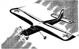 Simple, easily repaired, volatile, inexpensive… That’s only part of the requirements for training RC model aircraft. These requirements are fully satisfied “Trainer-RC” — RC plane engine with a working volume of 6.5 cm3 type of MDS or 0.S.MAX-40LA.