The basic layout of the appearance and settings of the wheels, obtained through long sketches, are clearly visible on these images. Our model has a generic nature; not tied to any particular modification, only the main observed signs of the race of the century. Therefore, the issues of copying and imitation of external nodes, we shall not stop, as it all depends on the taste and abilities of the modelers. I would like to note that the apparent complexity of playing such polyopia really quite simple and, moreover, a very “tasty” work. A good result can be achieved using the drawing paper, cardboard, celluloid and wood.
Much more important is the development of the chassis. The illustrations accompanying the article, shows two variants of the power plant model the class RM-2. First, odnovolova scheme, easier to manufacture, although it requires careful accurate work, especially in terms of the gear angular gear. No less important in the Assembly of components to achieve the rotation of all axles and shafts was easy, smoothly and without pulsation. Mounting the front end of the harness is designed so that when folding removable imitation body can grab the protruding ends of the pin harness with hook-shaped drills, and then, with a large (two-threefold) hood, all the rules to tighten the rubber motor. Without removing the pin from the hook drills, put in the plug of the bracket and then withdrawn . the hook is very convenient. By the way: the next machines we plan to additionally install the stopper of the drive wheels, which will further simplify the operation for winding the rubber motor. Then you don’t have to worry about holding torque and putting the model to the starting line, only to remove the stopper.
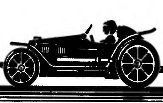
R and S. 1. General view rezinomotornaya class model RM-2:
1 — front wheel, 2 — wing, 3 — simulate fuel filler, 4 — simulated body, 5 — imitation exhaust pipes, 6 — frame with decorative moldings, 7 —clamp mounting exhaust nozzles, 8 — windscreen, 9 — wheel, 10 — headrest-fairing, 11 — rear (driving) wheel.
R and S. 2. Power unit chassis with one harness rubber motor:
1 — contour of the front of falcata, 2 — removable pin for winding the rubber motor with pre-tension (D16T), 3 — bracket pin (D16T, profile), 4 — frame (plywood), 5 — harness rubber motor, 6 — lug for holding the folded half of the harness (D16T), 7 — bearing 4×11, 8 — shaft (steel and 4 mm), 9 — spacer (brass), 10 — axis wheels (steel 0 to 3 mm), 11 — restrictive sleeve with a pin (brass), 12 — bracket (D16T), 13 — an outline of the window in the frame 14, the leading bevel gear 15, and the driven gear, 16 — bearing (bronze), 17 — remote bushing (brass), 18 a bearing housing (brass), 19 — screw spacer, 20 — the place of installation wooden brackets for the front axle wheels, 21 power screws attaching the bearing housing (from the final Assembly to put epoxy resin as the case is).
R and S. 3. The power section of the chassis with three rubber motor harness:
1 — contour of the front of falcata, 2 — removable pin for winding the rubber motor with pre-tension (D16T or steel), 3 — notched the bracket under the pin (D16T), 4 — the outline of the recesses for the rubber motor harness, 5 — screw fixing with countersunk head, 6 — frame (plywood), 7 — the place of attaching the bracket to the axis of the front wheels and 8 harness resinators, 9 — eyelet for holding the folded half of the harness (D16T), 10 — intermediate shaft (steel 0 4mm), 11 — bearing (bronze), 12 — corpuspetition(D16T), 13 intermediate cylindrical gear, 14 — axis bracket wheels (D16T, profile), 15 — center of the intermediate cylindrical gear (fixed pin on the rear of a leading bevel gear), 16 — circuit through Windows in the frame.
Second, trehgroshovaya modification more professionalized and may be considered as a reference in terms of a potential speed capabilities. As it is applied to complicated gear scheme, the construction of these machines more difficult — making it is possible to offer only to those who have already gained enough experience in working with different materials. I would like to note that the very design of the undercarriage of this modification, we do not consider ideal. Surely someone will come h the conclusion that the individual nodes can be solved in another way, easier and more efficient. However, the overall trehgroshovaya scheme, it seems, out of competition. The only thing you can try to improve it — to raise the energy of the model due to the length and cross section of the bundles. But it must be borne in mind that the length of the harness will increase slightly, and the growth of the cross section of the rubber motor (separate, alternately tighten harnesses) can lead to such a large torque moments, what with the charging handle will not athlete-student. After all the efforts of the pre-stretching of the rubber and the torque on the drill is very high!
In conclusion, given tests of the reliability of the movement of the machine in the boost sections of the road. They show that trehgroshovaya model needs to fill in the area leading roles. Otherwise (which, incidentally, was confirmed by trial runs of the constructed model) because of the unavoidable vibrations and reduced traction with the floor is scrolling at the start. As a result, not only lost the most energy-intensive the turns of the winding of the rubber motor, but often lack the range of speed. But the last still in the project laid a large margin! By the way —this was done intentionally, with the expectation of using the middle part of the chart work harness (see “M-K” № 5 for the year 1991, the material “Secrets of a rubber tourniquet”, Fig. 3, plot 2 on the top diagram). However, the NAC was, our car is not too parametrisierung, and to improve the result it is possible to spin the motor up to prekatrina state.
On trehiglaja chassis, we used the same scheme with removable front pins, allowing harness to stretch before starting. As already mentioned, separate the harnesses tighten alternately. Thus the rubber may RUB on the edges of the holes in the front bracket, so all edges of metal parts in contact with the harness needs to be carefully polished and oiled with castor oil.
In the future, we now work on simplifying the design of the chassis and frame while maintaining the General scheme. All new developments are compared by the efficiency and rapidity with the proposed option, which is probably for a long time was really a reference.
In conclusion, I want to make the readers interested in the problems rezinomotornaya the car, a kind of gift. The fact that we have an idea how to create advanced suspension for machines of the class of RM-1. The meaning of new items is the use of a flexible toothed belt with one end attached to the end tie-beam of a rubber string. Next timing belt is done through two-stage reducer increases, resulting in the rotation of the driving wheels of the model. With proper selection of parameters the timing belt (of course, use only line segment), its speed and the gear ratios you can create amazing energy machine of the class RM-1, which in the end can overtake even the best instances of the class RM-2. I think that to engage in constructive elaboration of this idea would be interesting for any automodelismo. Moreover, the proposed solution eliminates all the problems associated with the classical circuit with the winding of the thread on the shaft.
It seems that soon will arise another question: how to accurately clocking the time of passage of such a short distance at such a fast technique! But this is more a question for the judges than to the modelers-athletes.
V. SHUMEEV
Recommend to read ESCORT DESTROYERS Inevitably looming at the end of the 30-ies of the threat of war forced the British Admiralty to take all possible measures to strengthen the fleet, and to do this required quickly and... A SKEWER FOR… WALLPAPER Most of those who have decided to paste over the wall Wallpaper flat on their own, most often the whole day "bow" to each ordinary cloth, usually as a pack of cut of the Wallpaper... 
 Before you start the story about our new model of class RM-2, we want to go back a little and to remember with gratitude the publication in “M-K” № 5 for the year 1991, which was the first time in the practice of automodelisme describes the main design principles rezinomotornaya. It should be noted that many of the points of the article for us was, if not a revelation, then at least unexpected. This is especially true of the exploitation of the rubber motor harness, a choice of parameters of the chassis and check the nature of the motion models in the boost areas.