ROCKET – PARITEL’

ROCKET - PARITEL'In one of the rooms “M-K” in the report from the championship of Russia on model rockets, I noted the rocket plane category S4 Nikolay Tsygankov team in Murmansk region. I must say that the chosen scheme with a large wingspan (about 950 mm) and elongation of about 20 provides good performance as well. This contributes to the convexo-concave profile of the wing, and elliptical shape of the bearing surface when viewed from above. And external contours of the tail look perfect. All this allows to a minimum to reduce aerodynamic drag. Originally decided N. Tsygankov and the problem of drag reduction during takeoff model. He used double-folding “ears” (consoles) of the rocket and to prevent the occurrence of flutter of the fixed wing is folded in three points (instead of the usual – in two points), securing the third hook-latch on the tail boom.

Before starts models raketoplana many athletes skeptical about the flight characteristics of an aircraft N. Tsygankov. So, the coach of the Russian national team, honored master of sports Alexey Kurepin, whether in jest, whether seriously named this scheme rocket plane “provocation.” They say, will lead Tsygankov our “rocket scientists” in the wrong direction. But in my opinion, this diagram is the direction that we need to develop rakatomalala wishing to achieve success in this class. One thing I want to mention the manufacture of such models requires a careful approach to work and, of course, high technical training of the athlete-designer.
 
Model N. Tsygankova, I would have reacted to the so-called “Moscow” scheme. This is the folding wing and its turn for takeoff along the fuselage at 90°.
 
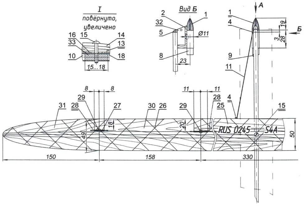
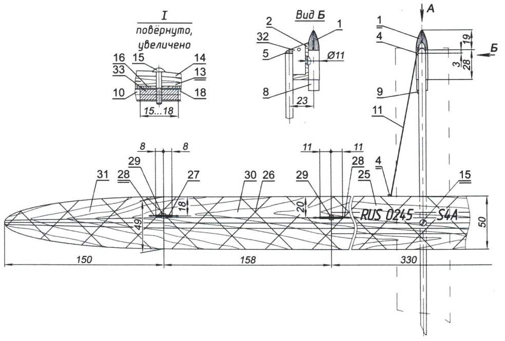
Now about the structure itself. The fuselage is made by a single technology of two elements: the nose part (body) and tail boom. Case vyklevyvajut on a cylindrical mandrel with a diameter of 7 mm. at the Beginning it is slightly heated and coated with a separating paste (“Edelvika”), Then impose “building” material. First glue one layer of glass (thickness 0.15 mm), pre-impregnated preform with epoxy resin. Giving the binder a bit to freeze, place one layer of carbon fabric, and another layer of fiberglass. After drying, the top layer carefully vyskazyvat and cut to length up to 160 mm. Similarly vyklevyvajut and the tail boom with a length of 443 mm, using a tapered mandrel having the smallest diameter of 2.5 mm. the two elements on the aluminum tube, the insert inside, with a length of 15 mm and a wall thickness of 0.5 mm with a diametrical bore for screwing the fastening screw of the wing.
 
On the subtle end of the beam attached tail made from balsa veneers 1.5 mm thick. First, glue the stabilizer. It elliptical shape in plan. On his left side at the rear of the cut brake with a maximum width of 26 mm. In the same place to it is fastened the rubber to deflect up for the forced landing of the model to the lower plane of the flap is glued cravings (determinator) – cut the fishing line diameter of 0.3 mm and a length of about 550 mm with a loop at the free end. Swivel flap with the stabilizer – on the sticky tape.
Kiel also carved from balsa 1.5 mm thick, covered with two layers of nitrocellulose lacquer and the butt is mounted to the stabilizer.
 
In the nose of the fuselage glued to the fairing, which is attached a hook for the elastic return of the wings in the gliding position. At a distance of 40 mm from it is second hook for hanging loop determinator.
 
To the bottom surface of the forward fuselage is glued on the resin VC-9 pylon, after making his big parties a small groove. Cut pylon balsa plate thickness of 6 mm. the location of the fibers along the smallest side. Front edge slightly round off, do in it a hole 4 mm in diameter, in which is glued a thin-walled tube, the edges of her clench. The lateral surface (the right in the direction of flight) almost all paste over with a foil. In this place attach the wick to the forced landing of the space Shuttle, and a strip of foil protects the pole from possible burnout.
 
To the lower plane of the pylon is glued container mrad. It vyklevyvajut of three layers of glass, of a thickness of 0.3 mm on the mandrel with a diameter of 10.2 mm. After resin curing, the mandrel is clamped in the machine and butt length of 28 mm. In one of the ends glued to the fairing with a length of 19 mm, which are drilled four damping holes of diameter 2 mm. (before the flight) stretch locking the thread, they also serve to vent the firing impulse from the lifting charge MRD, because the technical requirements it should not be separated from the model.
 
At the junction of the bow and the tail boom of the fuselage glue on top of the base plate, the wing length of 50 mm and a width of 7 mm, making it a cross hole with a diameter of 3 mm and following the groove on its lower surface. The upper surface of the pad is covered with a thin layer of epoxy resin – a smooth surface is required to reduce friction at the wing pivot.
 
Model rocket modeling class Ѕ4А champion of Russia N. Tsygankov (Murmansk)
 
Model rocket modeling class Ѕ4А champion of Russia N. Tsygankov (Murmansk):
 
1 – fairing; 2 – pole MRD; 3 – tube-piston; 4 – hook; 5 – cone of the fuselage; 6 – damping hole; 7 — container MRD; 8 – MOP; 9 – hook fastening elastic return of the wing; 10 – forward fuselage; 11 – the elastic return of the wing; 12 – emphasis of the wing; 13 – pylon wing; 14 – wing profile; 15 – the screw of fastening of the wing; 16 – base area; 17 – lock the folded wing; 18 – tail boom fuselage; 19 — thrust deterministic; 20 – stabilizer; 21 Kil; 22 – rubber of the brake flap; 23 – suspension of the brake flap; 24 – speed brake; 25 – the center section of the wing; 26 – uglenite (reinforcement of the wing); 27 – the elastic return console; 28 – hook; 29 – panel; 30 – medium console; 31 – external console; 32 – thermal protection of the pylon (foil); 33 – connecting bushing

 
The wing is made of balsa plate with a thickness of 2.5 mm and a width of 50 mm. First make the center section. Billet length 330 mm handle on top, pressing on its convex surface. While slightly round off the nose and gradually reduce the thickness of the middle plate to its rear edge. Then the plate is moistened and dried on the mandrel (you can use the tube diameter 55 – 60 mm), thereby imparting a concavity to the workpiece for the wing. Its absolute magnitude is 1.5 mm. the same method is used for preparing the plate for consoles, only its length is 320 mm. Further, this item cut in half, fold along the lower (concave) surfaces and treated by the circuit. Finally, both billet (center section and consoles) armintrout along the carbon filament, pushing it into the wood. The center section will need five threads on the console or three. Not having to dry the resin, glued cross-thread. After drying, turn over all wing planitu – to enhance the edges.
 
From the bottom, in the middle of the center section glued the pylon balsa plate with a width of 7 mm and a thickness of 3.5 mm to the front edge and 1.5 m at the rear. Then the center drill hole with a diameter of 2.5 mm (the axis of rotation and wing mounting).
 
The console in this model – the original. They have one more folding. After treatment (reinforcement and lacquer coating), each console is cut in half (to 160 mm) process the end surface and is connected pivotally under the outer angle of 9°. Soprikasalis surfaces (both ends) coat epoxy resin (for rigidity) at a distance of 8 mm from the edge. At a distance of 18 mm from the leading edge in every detail of the glued hooks for attaching the bands return. Where you touch the rubber bands to reinforce the linings of fiberglass with a thickness of 0.5 mm. Swivel elements consoles produced by gluing strips of nylon fabric on their lower surfaces, applying glue BF-2 or “Moment”. The connection angle test pattern. It needs to be 171° (an internal corner).
dock the console center section. The connection angle is 9°, swivel hanging them on strips of fabric. The joints are also glued hooks for rubber bands return. The distance between them is 22 mm from the leading edge to 20 mm. Assembled wing after checking the angles of the “V” attached to the fuselage with screw M2,5 flat head with a diameter of 7 mm.
 
The completion of the whole model determine the position of the center of gravity. It should be located at a distance of 20 mm from the leading edge. And of course, balancing to do, pre-securing sleeve from the burnt (used) MRD.
 
Then you need to run the model for planning and achieving sustained flight. When pitching you’ll have to load the bow. When you dive a little trending up the rear part of the stabilizer. Training cancer
the toplan to start producing in the following order. First bends terminations consoles down, applying them to the bottom of the “ears”, then both “tab” also bends down when applying it to the lower plane of the wing.
 
Folded thus the wing rotate counter-clockwise 90°. Hold it in this position, tie a string threaded through a hook on the outer part of the wing, through the damping hole of the fairing. Thus the wing is located along the fuselage to the takeoff position.
 
The Rocket Plane N. Tsygankova has a simple automatic forced landing. The principle of its operation – transfer model of stable gliding flight mode kupirovaniya with turn by turning up brake flaps on the stabilizer. Rejected flap after burning the wick thread that holds the thrust (determinator), and under the gum it is deflected upwards.
 
Before the start of the model MRD tightly inserted into the container and light the wick. Previously the length of the wick tortsujut on the speed of combustion, choosing the right size for flight time. Flight weight of the model without MRD is 20.5 g.
 
V. ROZHKOV

Recommend to read

  • FLYING CRUISER OF THE JAPANESE FLEETFLYING CRUISER OF THE JAPANESE FLEET
    The seaplane Kawanishi H6K and H8K. On the eve of the Second world war, Japan was among the few countries, which fleet was armed with large multi-engined flying boats ocean class. The...
  • ONE-WHEELED TRACTORONE-WHEELED TRACTOR
    Compactness, maneuverability and good traction — the undoubted advantages of the one-wheeled tractor created at the station of young technicians in the city of Novotroitsk. They managed...