An attempt to breathe new life into an “extinct” division made of the boys in our circle. Almost the very first attempts to create something of their own original brand of “children’s” cars with the rubber motor running on a sprain, sparked the interest of peers. I hope that it will be passed to you when you meet with the proposed development. Especially as children seem to us, not only managed to reach a new design and development techniques, but the simplest technique to give an amazing ride quality (which can confuse even the drafters of the “Rules on the self-similar sports”!).
To the question about the design of the machines of class RM-1 (in accordance with the rules of this circuit model cars with rubber engine tension) we will come back later. And at first about the main thing — suspension.
Rezinomotornaya model the transition of a subclass with the simulation body in the form of a modern race car:
1 — simulator of nasal air intake; 2 — wing front; 3 front wheel; 4 — body; 5 — transparent visor; 6 — simulators side of the radiator; 7 — the headrest; 8 — the simulator output channel of the cooling air (optional); 9 — “puck” wing; 10 — wing; 11 — wheel leading; 12 — wing.
The design of the chassis of the model (preliminary version):
1 — the base of the chassis (blank gluing four layers of plywood s1); 2 — idler pulley; 3 — location of the harness of the rubber motor and intermediate filament; 4 — charge pressure (brass, sheet s1); 5 — screw M2,5; 6 — front axle (steel Serebryanka, wire Ø2);
7 — washer (brass, solder on the axis); 8 — the bearing of the front axle (bronze tube Ø3);9, 10, 11, 16 — the bulkheads of the hull (plywood s2); 12 — bracket, rear axle (aluminum profile); 13 — the bearing of the rear axle (bronze or broseker-Mika); 14—rear axle (Serebryanka, wire Ø2); 15 — spassiba for fastening the yarn end of the rubber motor; 17 — remote washer (brass); 18 — hub rear wheel (duralumin, axle to put on the thread with a sizing compound epoxy resin); 19 — tire rear wheels (microporous rubber); 20 — lock nut safety; 21 — front hitch the front end of the rubber motor; 22 — front wheel hub (made of anodized aluminum, the axis to reinforce epoxy resin); 23 — the tire of the front wheel (microporous rubber); 24 — the axis of the guide roller (steel SPECint M3); 25 — the case (Vileika of paper or paperboard).
In fact, it as an essential part of any sports model has not undergone revolutionary changes. The same rollers, which is conducted through an elongated rubber band, the same system drive axle wheels with the winding on it when running and attached to the harness thread. Here, for efficiency and simplicity have long found solutions, we have nothing to add, except that the energy-intensive use of modern varieties of rubber and inserts of broseker-Miki or PTFE in bearing assemblies. Indigenous improvements as speed and distance indicators speed was achieved at the expense of only one change — replace “standard” nylon thread Kevlar. Now this material, sometimes referred to as SVM, has become much more affordable than two years ago, and its use can be recommended even for school models. So, it is Kevlar thread allowed to become the energy of the microcosm is simply unrecognizable. The fact is that with a relatively small thickness (we used a braided thread of the SVM has a diameter of about 0.1 mm to more precisely measure this dimension failed because of the flattening material measuring tools), it has fantastic tensile strength at break of approximately 70 kg!
What gives? Judge for yourself. As an example, consider the specific design shown in the drawings. With two by-pass roller the total length of the engine is about 600 mm. If the coefficient of expansion of the material of “engine”, which is for the best varieties of rubber reaches 900 percent, with a small margin of strength to take the length of the harness, equal to 100 mm (in this case, the stretch factor can be up to 600%). This means that on the driving axle can be wound 500 mm long intermediate filaments. Or going to more interesting to us criteria, with the diameter axis, 2 mm on it can be wound up to 80 turns of the same thread (it is useful to note that when the turns of one-to-one total width of the winding is only 8 mm!). Now it is easy to calculate and a traversable model of the way when one fully wound motor. It is equal to 12.5 m. Thus, at a distance, passable model, we, however, almost without reserve, satisfied the requirements of the rules of the competition in the class RM-1.
Well, it would seem? Standard design, typical results… But remember, the strength is Kevlar thread. Based on this value, reasonably assume that a valid cross section of the unstretched rubber motor can be 70 mm2. The force of stretched rubber harness will just be equal to 70 kg (or rather, slightly less to the required margin). And now imagine what happens with two-millimeter axle, if it is applied a transverse load of specified magnitude. Of course, it will simply bend. Output in the introduction to the running circuit of the step-up gearbox with a gear ratio of i=0,5. It is easy to recompute the new drive characteristics. Conventionally, keeping the same diameter of the “drum”, on which thread is wound, get a new value of the distance range — 25 m. Thus, even overlap the requirements in the class RM-2 (three-dimensional model of the car with rubber engine twisting).
What with the rapidity of a model? Let’s calculate at first seeming meaningless to the “children” of micromachines the size of a potential acceleration at the start. It depends on the ratio of the diameter of the “drum” and wheels, from the gear ratio of the gearbox, the maximum tension of the rubber harness and the total weight of the model itself. As a result of simple mathematical operations while the mass of the model 700 g get a… 10 d! This energy does not possess any of the known machines, whether a real car or any car. To imagine this amount, it is enough to note that modern jet fighters during the execution of the “cool” maneuvers overloaded 8 g — in excess of its pilot temporarily loses consciousness.
The result of the above calculations is the question: with the accelerating force of 7 kg to prevent slippage of the drive wheels of the model? The answer is simple: nothing. You must either load the model almost up to 7 kg in mass or respectively reduce the cross section of the rubber motor. Of course, you can go some other way. Enough to raise the transmission coefficient of the reducer is at least three to the coefficient of expansion of the rubber under all other constant parameters was reduced to 400 percent. Then the rubber motor will have less wear, and the maximum force on it to fall to 2.5—3.5 kg (the dependence of force from the coefficient of expansion of model grades of rubber are clearly not linear, especially in the area of maximum elongation).
Templates of the bulkheads of the housing (part numbers correspond to the positions of figure 2).
Drive axle (upgraded to the final version):
1 — bracket right (steel profile); 2 — a leading gear; 3 — axis-“drum” (Serebryanka, wire Ø2); 4 — driven gear; 5 — housing; 6 — axis back (Serebryanka, wire Ø2); 7 — housing ball bearing (brass; pan, part 1); 8 — housing-right bearing (soldering on parts 9); 9 — left bracket (steel, channel); 10 — idler pulley; 11 — the remote washer.
Running rolls:
1 — video (aluminum); 2 — bushing-bearing ((ceramics, extruding in item 1). Unspecified dimensions are chosen arbitrarily.
So, what have we got? From the field of ancient car we moved, figuratively speaking, almost the next day. There seems to have been more situations where the potential of the machines would have to artificially reduce even due to the grip. Thus it can be seen that there is another way of implementing the proposed severenergiya machine. It jumps to the large values of the gear ratio of the reducer with a corresponding increase in the length of the passable model distance to 100 m and more.
As for design features, they are, in General, and no, all nodes are quite traditional and familiar automodellista. Therefore, please note that the diameter of the “drum” that we had left within 2 mm. the fact that the huge efforts to develop rubber motor specified or even twice reduced cross-section, a traditional shaft bearings wear out too fast, and the friction losses are too great. So we switched to using ball bearings. And given the width of the winding of the filament along the axis of the “drum” is equal at two-layer stacking of about 3 mm, a deflection of the shaft can be neglected. The intermediate rollers are located on the hard axis in pontocircassica bearing ear — here the speed of the parts is much less, and friction losses are not so significant.
In conclusion, a few words about the design model. Considering that we are in the circle managed to create a promising chassis with unique driving characteristics, as it is inconvenient to establish a simplified flat “appendage”. So we went the way of the modern racing simulation “race car” one of the most popular “formulas”. And developing a simple simulation body, it wycliffes of the most accessible and simple materials — cardboard and thick drawing paper. The bonding of one body leaves only two nights, although the external finishing and painting take a lot more time.
Competition with similar micromachines class RM-1 we perform on an equal basis and simultaneously with the RM-2 according to the rules of the past (of course, with the measurement of the maximum speed on the basis of 20 m). The previous designs of the class of RM-1 steel is indeed “living history” and now just gathering dust on the shelves of the circle.
Maybe someday we will see that these subclasses car out of the framework of the “simplest” and take over their rightful place in the list of classes.
V. ZAVITAEV, the head of the circle of automodelisme
Recommend to read FOURTH – ONCE Usually mention the proverbial fifth wheel. However, some automakers use a formula, reflected in the name of our material. They really believe the fourth wheel in the car superfluous.... “WE WERE SHAKING THE BUSES CLOSE…” City bus ZIS-155 production in 1949. The development and expansion of cities accompanied by the concentration of citizens in residential areas and, consequently, the factories in the... 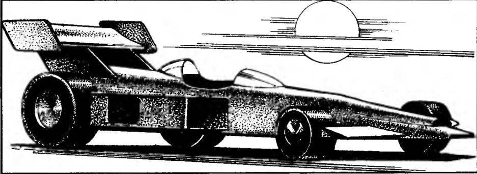
 When among students who have mastered only the basics of the original automodelisme, comes to talking about the class of simple machines, rubber motor, it is submitted immediately think “sophomoric”. They say, in the age of radio, heavy duty electric motors and internal combustion engines are very popular and widespread at the time the class is now an anachronism and good except for exploring the world of car.