 Schematic flying models — the basis of mass sports: Effective speech with “sketchy” the competition gives right to assign the Junior category. The first such model with rubber motor was created just 12 years before the flight of the first aircraft Mozhaiskogo, i.e. in 1870. So what should the modern student to repeat what a hundred years ago managed to create only a talented engineer?
Before you start making models, please read the entire article and prepare the material base “construction.” You’ll need: small metal planer, pliers, a file, sandpaper, whetstone, whetstone, knife.
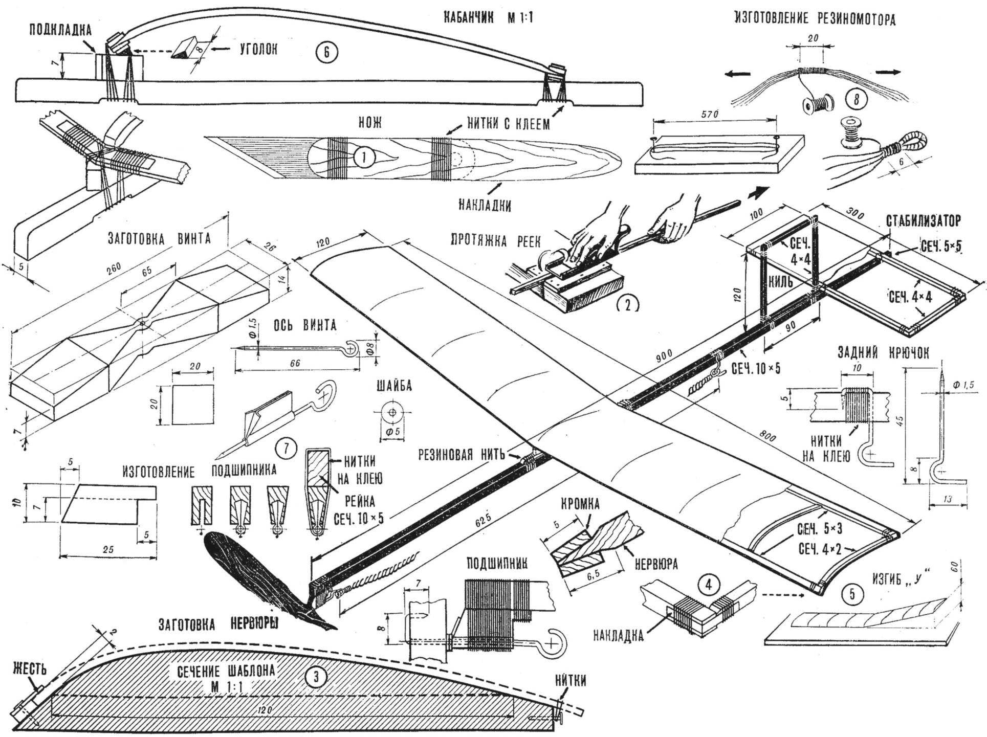
It should be noted that a pocket knife for work can be inconvenient and even dangerous because it can accidentally occur. For the construction of the model it is better to use a homemade knife made from an old saw blade (Fig. 1). During the processing of a tool on grinding machine, try to avoid overheating (blueing of the metal), especially at the end. Note that no bar for sharpening and grindstone for dressing the glands of the plane and knife construction of good models impossible. The condition of the tool depends largely on the quality of work.
From the materials we will need strips of grained pine, lime bar for propeller, steel wire Ø 1,2—1,5 mm, thread (white), glue, tissue or other thin paper and rubber thread (flat or round) for the rubber motor. Glue is desirable to have two varieties: for gluing wood and for gluing paper as the wrapping. For wood a good nitrogly AGO. It can be replaced with a solution of celluloid in acetone or nail Polish.
The following stage — preparation of working drawings (design documentation will serve as our publication). First watertite wing and stabilizer (top view), Kiel (side view) life-size in accordance with the specified dimensions
Traditionally, the construction of conceptual models start with the wing. To build the necessary rail section 5×3 mm. In the circle they can be saw on a circular saw (observing all safety rules). For the manufacture of rails at home is recommended to make a special fixture for broaching (Fig. 2). This is the Board mounted on the Desk or in the vise, it is stuffed with strips (plywood, cardboard), forming a groove of the required depth. Rail, prepared with an allowance of approximately 0.5 mm on the side, put in the fillet and holding the plane with one hand, stretch it. The chips are removed as long as the section of rods is greater than the depth of the groove.
To make the ribs of the profile shape of the wing from a piece of wood with a plane and a file, make a template (Fig. 3). The wing profile is a smooth curve, the maximum height of which is located on the first third of the chord width equal to one tenth of its value.
Blanks for ribs steamed for 5-10 min in boiling water and keep in the template until they are dry, and then cut to size and sharpen the ends. These ends of the ribs are fixed on the glue in the split knife edge the leading edges of the wings. The place of installation of the end ribs should be reinforced with strips of tin from a tin can the size 30X2 mm, attached with thread and glue (Fig. 4).
After gluing the wing ribs attach to the transverse “V”.
This is required for steady flight of the model. To the front and rear edges near the middle of the rib at the top and bottom threads on glue, attach the strips of sheet metal the size of 30×4 mm before the glue dries, fold them so that one end of the wing climbed above the slipway at 60 cm (Fig. 5).
The wing is mounted on the mounting rail via the horn, which provides the necessary angle relative to the longitudinal axis of the model. This angle is 3° (linear exceeding the leading edge of the wing above the rear — 7 mm).
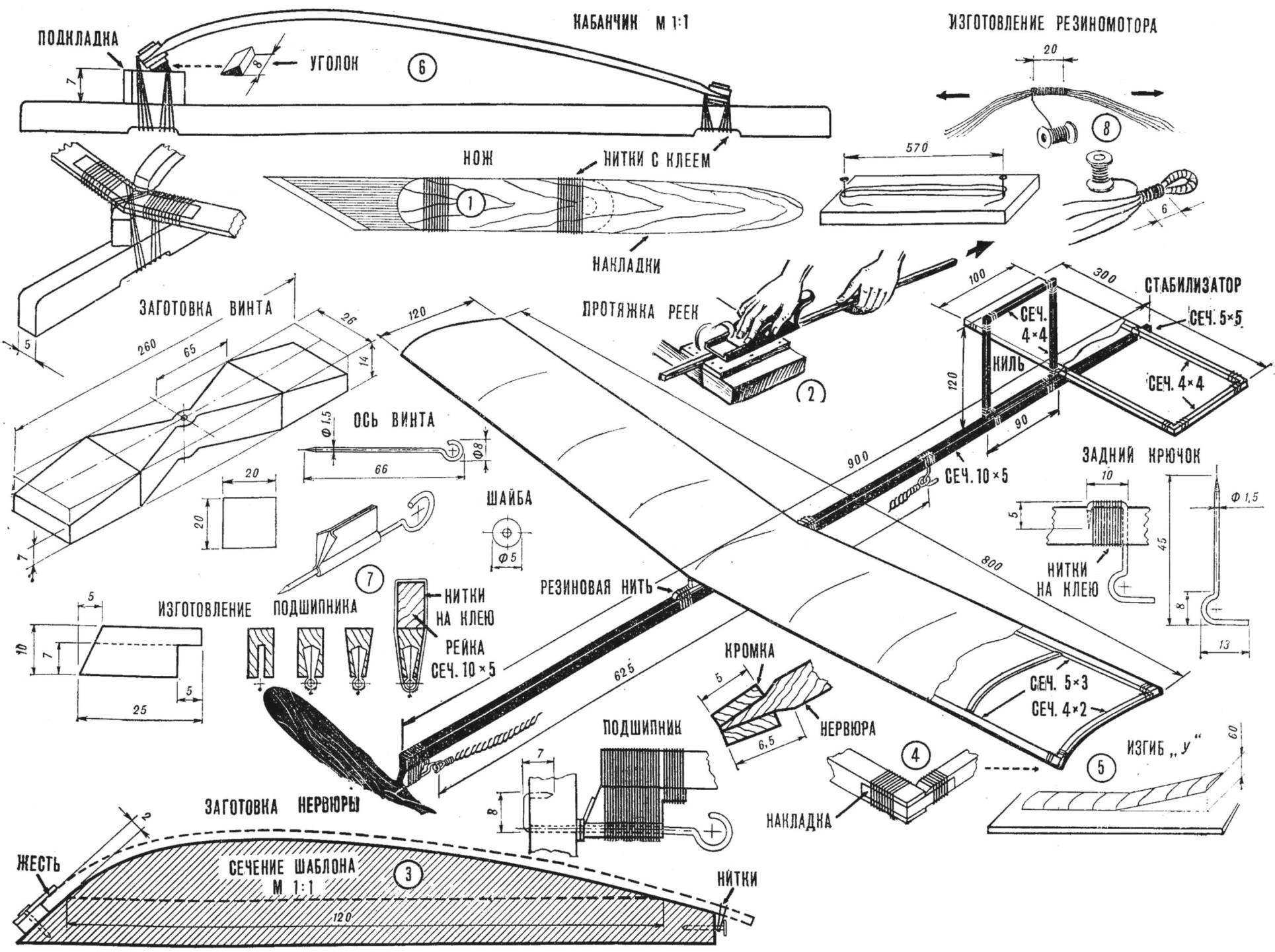
Pylon (Fig. 6) made of pine or basswood and fastened to the wing thread on glue. To the rail the pig is attached with a rubber thread.
The manufacture of the stabilizer and fin is self-explanatory; they are attached to the rail tightly with thread and glue.
The fuselage of the model rail, the cross section of the tail which is behind the rear hook of the rubber motor is reduced: it is not transferred stress from the rubber motor.
Screw mounted to the rail via a bearing. First produced axis of the screw with a hook for connection with the rubber motor. Along the axis of the sheet from the curved bearing (Fig. 7). If you build in a single node the axis is pressed into the body of the screw. Don’t forget to install between the bearing and the axis of the screw two or three washers from sheet metal to reduce friction.
The axis of the screw must be parallel to the axis of the model or to have a small negative angle (tilt down).
The rubber motor consists of 30 strands Ø 1,5 mm. Can be applied the rubber band. The number of flat yarns depends on their section, but in any case their weight should be about 25-30 g of Rubber thread freely without tension fit between two nails driven at a distance of 570 mm. Then the ends of the rubber motor wrapped with thread, as shown in figure 8. The free ends of the strands are cut.
The wing and stabilizer hang tissue paper only from the upper side, and the keel on both sides. Before tight have to check that there are no distortions. Better to use a slow-drying, sticky adhesive. Silicate stationery glue suitable for this.
The wing is attached to a rail after balancing. The center of gravity of the model should be placed on the one third chord of the wing, that is 40 mm from the leading edge.
You can now start the adjustment of the model for planning. Model take a few behind the center of gravity and a little push, a little by tilting her nose to the ground: If the airplane immediately drops flat, it means that too weak was the impetus. If the model is rapidly shoots up, and then randomly falls to the ground — the push is too strong.
With the right launch, the plane will fly in a straight 8-10 m and, gradually decreasing, gradually lowered.
Try a little to move the wing forward to give the model back alignment, or back, creating a front. Let’s see how this affects the nature and speed of flight. Ask how the flight affects the installation angle of the wing.
Take your time to get the rubber motor, learn how to run and adjust the model during the planning process. The number of turns of turns of the winding of the rubber motor should increase gradually. By the way, if you have difficulty with the acquisition of rubber for motor or manufacture of a screw, for starters, you can restrict the construction of a schematic model of the glider, which is enough to load the front of the rail.
S. MALIK
Recommend to read
 WITHOUT STANGELY 0.1 MM
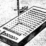
If your stock of drills is quite diverse, it is more convenient to place them on the wide wooden bar on the principle of a grid. The advantages of such vertical storage is obvious: the...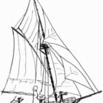 TABLE-NAVY
When building sailing models of the greatest difficulties arise when equip with their "small things": blocks, lanyards, dead eye. I also spent a lot of time to produce so-called...
