
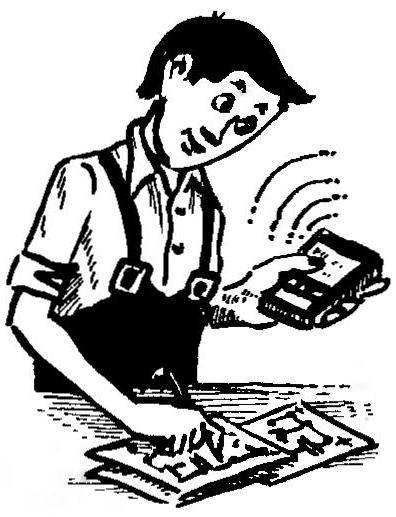
 Digital multimeter in a new role. Inexpensive digital multimeters M-830В today widely used not only in industry but also in everyday life: for example, to measure the voltage in the network or at the terminals of the battery, the “continuity” of electric circuits. Supplemented with consoles, developed by radio Amateurs, they also find application in the measurement temperature, frequency of rotation of the motor shaft…
Among the devices, allowing to use the popular M-830В for him in the unusual role that applies my proposed design. This is a homemade box, designed to improve model multimeter so that the user has the ability to simultaneously conduct measurements to control signal actuating device or mechanism upon reaching a predetermined value of the parameter under control.
The result is easy to turn, for example, measuring temperature in the thermostat, and the usual power supply unit — network adapter overcurrent condition or voltage. You can even produce the required switching of the device to achieve a controlled magnitude threshold. As practice shows, the accuracy of such actuation is determined by the characteristics of a basic multimeter (or rather, applied it analog to digital Converter ADC, made in the form of a large chip) and will not be worse than units of the lower discharge at any limit of a range.
The ADC has no outputs signals of the digital part, so the number of features of the consoles — comparison of the logical levels at the connection points of the liquid crystal display (LCD) is available in the multimeter, with levels of the same name exits “storage” 3,5-bit decade counter operating in tandem with the decoder 7-element code.
The console is designed for connecting it to ADC type КР572ПВ5 (IСL7106), but can equally successfully be applied with any device having digital output. To reduce the number of comparison outlets in the circuit are considered the property of redundancy of a stylized representation of the numbers. The essence of the latter is that any such character can be determined by the status levels of all five outputs a, b, e, f and d standard notation of segments. Thus each digit will be converted to its 5-bit code, and the 3.5-times-row number will be represented by 16-bit code.
In principle, any number can be expressed with only four digits in binary. However, the transducers 7-element code in the BCD complex, so the design of this design preference is given to more simple, the above solution. Describing him. it is useful also to note that the logical signal at the output of the prefix is generated only if the equality compare of codes, and changing the number on the unit does not lead to a proportional change in the code.
Made this console in the domestic IC 176 and 561 series. As can be seen from the circuit diagram, DD1 performs the functions of the counter-frequency divider 10. The storage counter is collected on three identical circuits DD2 — DD4. The trigger signal conditioner display unit of the senior class is DD5.1 with the logical elements DD6.1, DD6.2; a control sound generator — DD6.3, DD6.4; chip comparison, binary codes — DD7 — DD10; a trigger, which sets a threshold level, — DD5.2. The diagram shows simplified connection of additional LCD HG1, allowing threshold setting directly in the process of measurement.
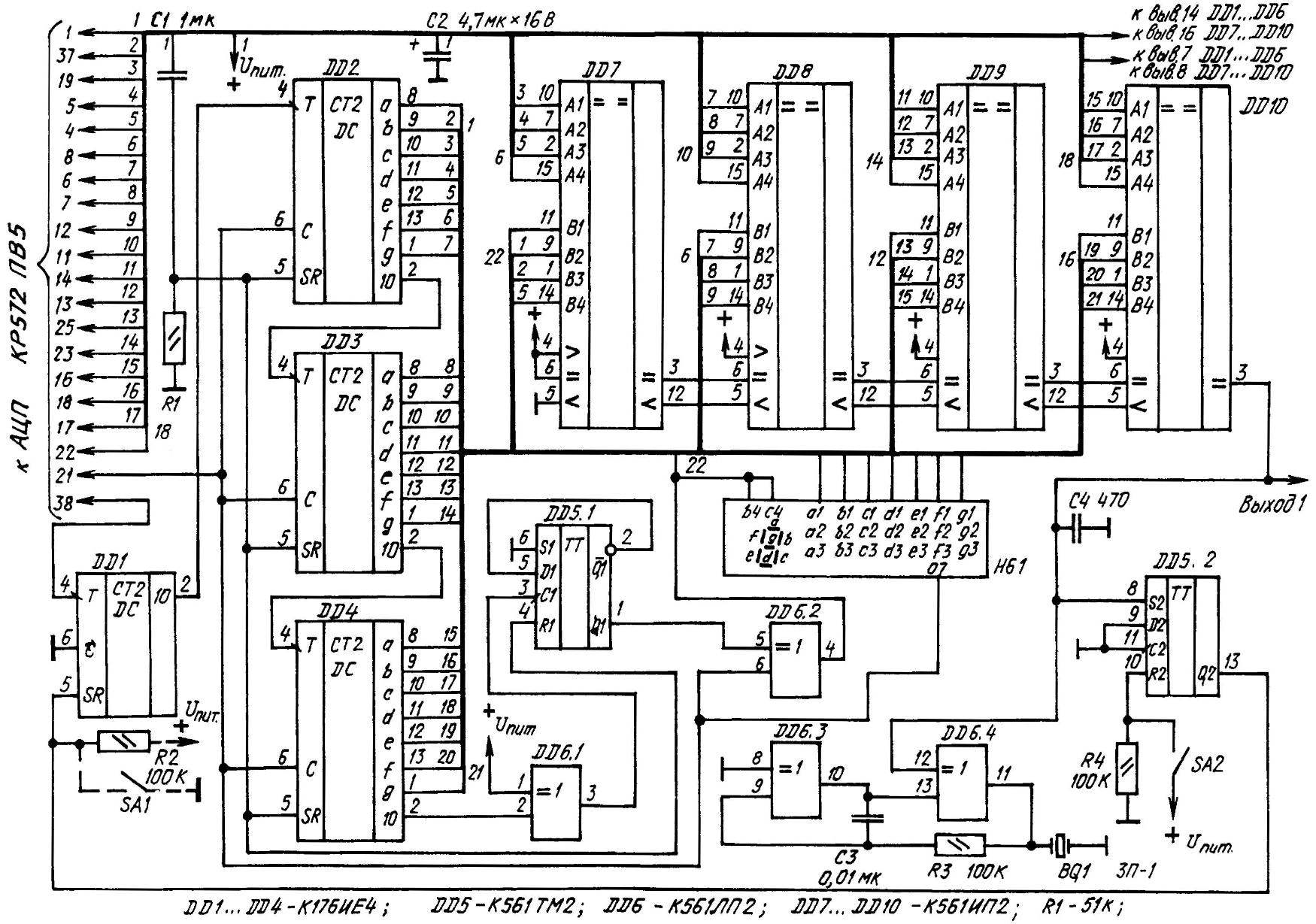
Electrical schematic of a homemade console to the digital multimeter, significantly expanding its real capabilities
Console podstegivaet to the conclusions of the ADC at the point of supply of the digital part (vyv.1 — plus, vyv.37 — minus common prefix), connection of the segments of the LCD (pins 4-8,11— 14, 16 — 18,22,23 and 25), a common electrode CE (vyv.21) and output signals of the clock generator (battery + 38). The point of connection of the segments (16-bit code analog-to-digital Converter) connected to inputs of And circuits DD7 — DD10, which are included in the scheme increase the bit compare codes. The inputs In the same IC the signals with the same outputs of memory counter consoles. In case of equality codes of the ADC and the storage counter output ” = ” DD10 appears logical one — output console.
Before “recording” the threshold level in the storage counter on the display of a multimeter set to a number corresponding to the threshold value. The number can be set by measuring any smoothly changing parameters: for example, the voltage taken from the engine of the variable resistor connected to the power source. After that short short contacts SA2.
As a result, the trigger DD5.2 switches to the state in which its direct output and associated input R DD1 will logic low, allowing the IC DD1 counting mode. On the storage counter output 10 DD1 will start receiving pulses, the number of which is indicated on the indicator of the multimeter.
When the output of the console log.1 trigger DD5.2 switch to the original state. The outputs DD2 — DD4 locks the code number of the indicator, which will remain there until another “rewrite” or power off the device.
At the same time log.1 will go to the top (the scheme) entrance DD6.4, turning it into the inverter, which will create the necessary conditions for the sound generator. Means are audio alarm recordings code threshold or reach a measured value of the predetermined threshold.
Logical element DD6.1 included in the scheme of the inverter. Its output signal switches the counting trigger DD5.1 at the time of overflow of the counter DD4. DD6.2, exclusive OR, converts a constant logical level of the direct output of the trigger in an alternating voltage with a frequency and phase synchronous with the changing voltage at the terminals b4 and C4 of the ADC. For the same purpose — to obtain the AC voltage at the outputs of memory counter — inputs of the chip DD2 — DD4, and conclusions.6 logic element DD6.2, is connected to the OE LCD.
To use your own LCD in the console make the following changes. The output of the trigger DD5.2 disconnect from the entrance of SR DD1. Is he connected another chain, conventionally shown by dashed lines in wiring diagram.
Entrance T DD1 “slack” on the output connect the MA LCD or any segment. The pulse repetition frequency at the output 10 will be only a few Hz. So there is a real possibility: while the contacts SA1 are closed off is to use a manual “dosage” of incoming pulses to a storage counter.
It is useful, I think, to emphasize that after separation SA1 code recorded in the storage counter is maintained until the next closing of the contacts or until power down. The direct or inverted output of the trigger released DD5.2 can be used as an additional output of the console. After resetting the trigger (by contact closure SA2) it automatically switches into state “1” — upon reaching the measured value of the established threshold.
Usup is supplied to the console directly from the power supply of the digital part of the circuit ADC and is approximately 4.5 V. However, for guaranteed chips К176ИЕ4 used as storage counters DD2 — DD4, is provided at a voltage of not less than 5 V. As practice shows, the “surprises” from these IMS can be expected mainly at the time of filing the understated Range. And to the outputs of the above counters with the advent of power could not be set in an arbitrary state, by means of a chain С1R1 is auto-zeroing: once you enable the console.
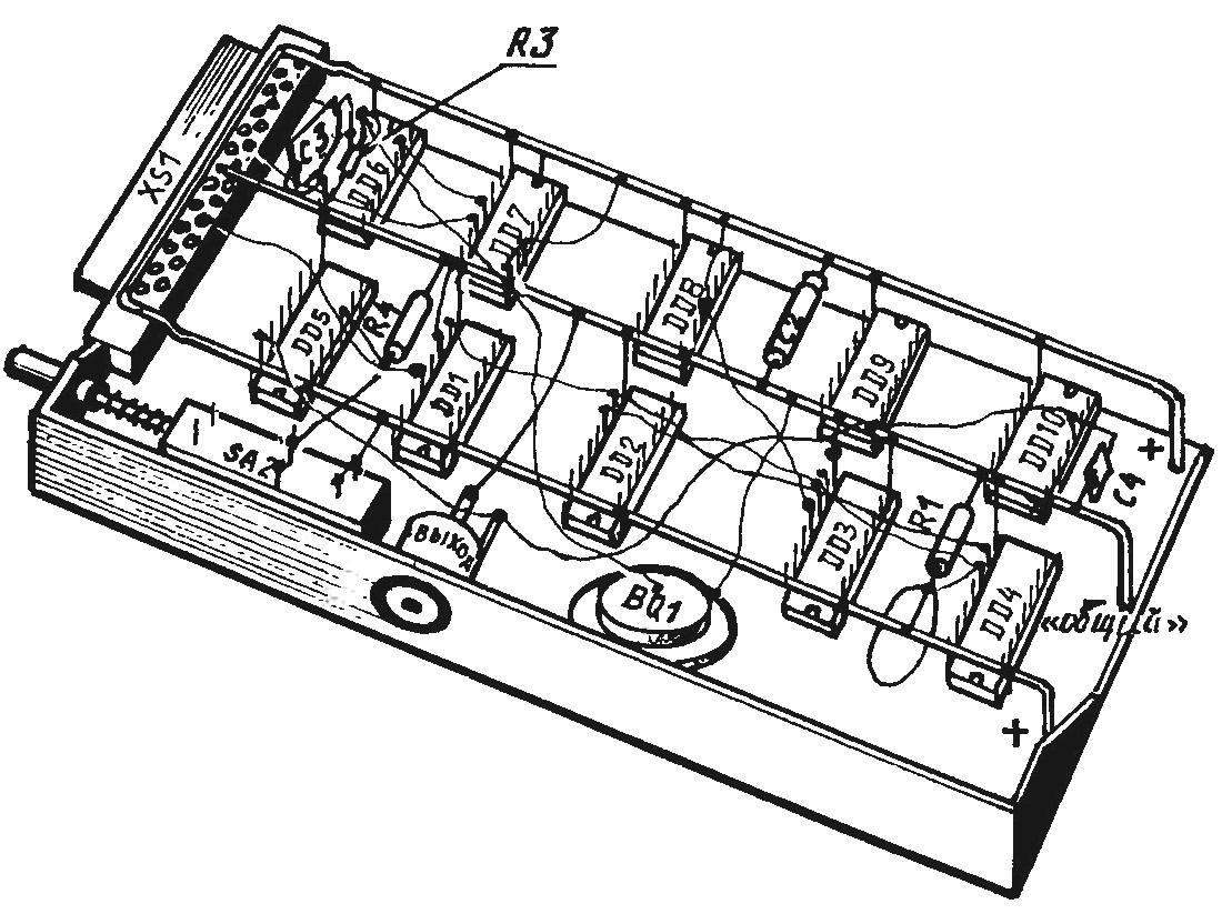
The installation conditions of consoles in hinged manner in the case of audio tapes МК60 (where the ration is conventionally marked by black bold dots)
Other features of this device it must also be noted that the capacitor C2 serves as a filter that protects the console from interference in the food chain. The purpose of C4 is to block the short voltage spikes that occur when changing code to the inputs of the And circuits DD7 — DD10. The capacitor C3 together with the resistor R3 are timing that their value depends on the frequency of the sound generator.
BQ1 — piezo buzzer designed to play a test sound signal. If necessary, disable the generator, you should use the input element DD6.3 (upper scheme) by disconnecting it from ground and then connect to the “positive” power bus boxes. Resistors R2 and R4 need to ensure that the inputs of the SR chip DD1 and R2 logic gate DD5.2 does not remain “suspended” when the open state of the switches SA1 and SA2.
As DD1 can use either binary or binary-coded decimal counter (for example, К561ИЕ8, К561ИЕ10, К561ИЕ16). Acceptable replacement and the rest of the chips: for the same series and 561 1561.
All resistors — it’s all available MLT-0,125. Capacitors also are not of the short supply. In particular, C1 — КМ6; C2 — K53-14 or similar, with a small leakage current; C3 and C4 — KM5 or any ceramic.
Not a particularly critical approach to the choice of piezo В01. Quite suitable, for example, “peepy” from watches, electronic toys, or a phone branded with acoustic design (audio return higher than that of analogues of domestic production).
Switch SA2 — small ПКН61-88. As the LCD is acceptable ИЖЦ5-4/8 or liquid crystal display from the digital scale automotive receiver. Importantly, each segment will had a separate output (the unused segments should be connected to the OE LCD).
Now a few comments about the installation. Of course, it can be printed. However, a regular user of the multimeter used to perform a mounted installation, in order not to have anything to do with the circuit Board etching chemicals, nor drilling 1-mm holes in the printed conductors.
For surface mounting you will need thin insulated wire (preferably in the heat-resistant, for example, Teflon insulation), cut two tin-plated 1-mm wire. Not do also without case from standard audio tapes, in a narrow side which you want to paste connector (Fig. 2).
To the extreme conclusions of the electrical connector is soldered U-shaped curved segment of the above-mentioned tin-plated 1-mm wire, which should now serve as a kind of bus “plus” the power of the console. The second segment, curved in the form of the letter G and is soldered with its long end to one of the Central insights of the connector, will play the role of “minus” type (“common” wire).
The distance between the parallel portions of the tire is set such that it was convenient to solder to them (respectively!) “plus” and “minus” leads of the chips, placed in two rows (5 copies of each). Then place the rest of the “large” radio and perform all mounting consoles according to its wiring diagram.
After completion of installation and validation of electrical connections install a second, slightly modified half of the cassette case. Bring the essence of the amendments is to make fully assembled console easily podtyanulis to the mating part of the connector, reinforced directly on the body of the multimeter on the bottom.
Naturally, the dimensions of the device after podstanovki to it consoles increase, but only on the thickness of the cassette case, which became the seat of the “advanced electronics”. And this is just an extension of 17 mm!
When removing the console socket part of the connector mounted on the housing of the multimeter serves as a stand. On the usability of the standard instrument it has practically no effect.
It is useful, probably, to stress the ADC console connects by using electrical connection with a flat multi-wire ribbon cable (the kind used in computers to connect the motherboard with a floppy drive). For original same podpici the cable end bottom housing cover of the multimeter was removed and it was made a cut of appropriate dimensions. Power supply battery at the same time, of course, disconnected. A soldering gun used compact, with a fine tip.
A. ROMANCHUK, the village Novikovo Sakhalin region
Recommend to read
 NAGS D-6
A happy event — acquisition the garden plot is often overshadowed due to the lack of supply on this undeveloped territory. In such situation I have made with chain sawing machine to...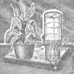 AUTODRINKING FOR COLORS…
Water-demanding plants and flowers require frequent watering, which is not always feasible, for example, in the holiday period. Available way out of such difficulties is a simple device...
