Model is going of the most affordable, abundant materials. Basic plywood and pine or fir, Linden slats. The frames, keel and stem is of a conventional construction plywood 4 mm thick. the Only wish is for the keel to choose the smoothest part of it, because symmetry about the future of hull is the first condition of good running properties.
The covering of body parts and add — ons plywood thickness 0.8—1.2 mm. If you get this failed her with success can replace homemade, glued together from several layers of drawing paper. Ironically, this ersatz material, in some cases, even better than plywood. Paper more water-resistant plywood, not less durable. Important and high quality white surface, advantageous in comparison to the wood surface that requires sanding, putty and protection from moisture (paper, usually impregnated through and through and thus becomes completely water resistant).
And is this stuff so. On the glass, protected from the adhesion of plastic film or cellophane, is placed the first sheet of paper and a brush it is applied to the mixed epoxy resin. Then place the next sheet, and so on until you reach the desired thickness. It is usually enough for four layers. The last leaf, of course, resin is not covered. “Sandwich” to complete the curing of the resin is covered with the second glass and pressed down the load. Such sheet material lends itself well to processing and colouring.
As a plant it is best to use ready-made industrial product consisting of a kit of motor, deadwood, propeller shaft and propeller. Before beginning the Assembly of the model need to solve, will be used as such or the drive nodes are you going to do on their own. And in General, you should not start building until you find all the necessary materials — this will allow time to consider the changes in size of some parts (slots in the frames are exactly the strips and the thickness of the plating, etc.).
The entire Assembly is microcode on a flat wooden Board measuring approximately 200X600 mm. it is best to Glue with epoxy. The duration of curing can be compensated by maximizing the number of connections running at one time. In some cases it is useful to conduct a “dummy” Assembly of the pieces on the points of nitraria, then to shed the seams with epoxy. Before starting work, it is useful to prepare the bars are glued with emery paper.
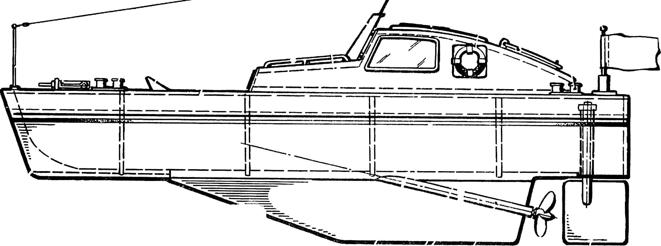
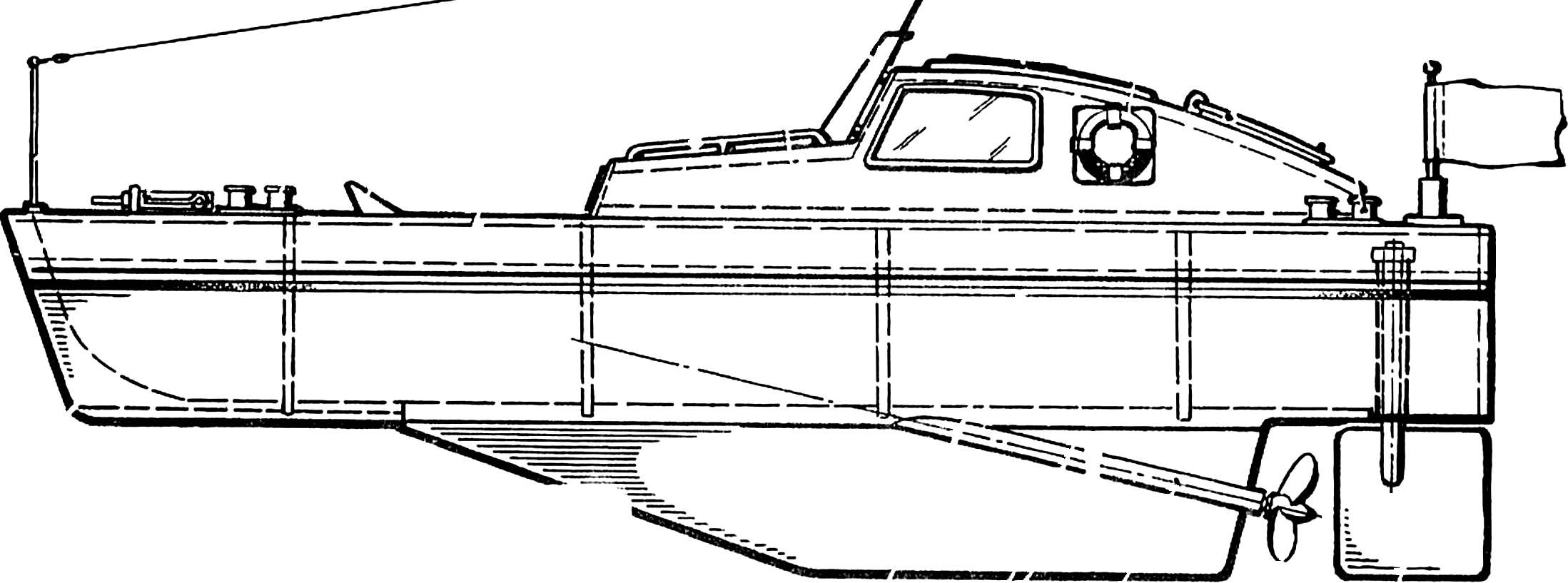
Fig. 1. Self-propelled model of a boat:
1 — antenna stand, 2 — anchor, 3 — antenna, 4 — cleats, 5 — balneoclinic, 6 — housing, 7 — rail 8 — deck, 9 — pole 10 — sliding roof of the wheelhouse 11 — lifeline 12 — cover, 13 — flagpole (installed on the switch; the arrow shows the direction of pressing), 14 — a wheel Assembly (pen, baller and ballery bearing-deadwood), 15 — propeller 16 — deadwood, 17 — details of keel, 18 — waterline 19 — the stem, 20 — hatch cutting, 21 grid, 22 — framing the cutout in the deck, 23 — frame cutting, 24 — sheet metal cutting, 25 — sample frame, 26 — stringers, 27 — V-rack, 28 — the shell plating.
Numbers in circles indicated the main section of the housing.
First, cut out all the frames, the nasal insert (stem) and both parts of the keel. The drawing frames are shown by the dotted line rectangular protrusions. Their purpose — fixing of the cross set on the stocks in an efficient position. Flush with the ledges are nailed wooden bars cross-section 10X10 mm, which is during the installation of the frames on the slipway, in turn, are nailed to the last.
The contours of all other parts after redraw in full size are transferred to the plywood (on the shell elements and add-ins word plywood equivalent can be replaced by “ersatz plywood”), neatly cut with a small allowance for grinding. Check the shape, size and position of the grooves under the stringers — they should extend slightly beyond the outlines of the frames, so after polishing the frame is formed a flat surface joint with the casing.
Fig. 2. Templates for manufacturing major parts of the model:
1 — stem, 2 — deck, 3 — frame strips, 4 — Kiel (shaded jumper be removed before installation of deadwood), 5 — side wall of the cabin. Frames, marked NR. 1, etc., according to the position along the length of the body correspond to the cross sections in figure 1.
The housing Assembly. First on the slipway to discourage the axis of the housing. From the drawing it can be transferred to the perpendiculars of the provisions of the frames. Using the bars section 10X10 mm (and they must not protrude beyond the contour width) frames are assembled on the slipway. After the control precision of installation on SHP. 5 is attached to the nasal insert, and the keel parts — V-rail. Between the last parts should remain the precise space beneath the stern tube. Last are placed the stringers, and all joints of the frame shed with resin in places not smeared with glue still in the Assembly. For the sealing of parts, you can use thin nails, pins and clothespins.
The casing frame. Assembled frame carefully filing and sanding. Then made templates of the pattern of the trim parts by the contour of the finished frame on thick paper. Cut the paneling is glued on the sides, and after the curing of the resin and Stripping the seams and on the bottom. If you are not able to match the elements of the bottom plating to each other, it is better first to cover one side of the bottoms and then another.
After removal of the housing from the slipway to remove the mounting bars from the frames, to remove the technological lugs and sanded the plane of the deck, and simultaneously to strip the sheathing joints.
Groove for locking the parts of the keel strip with a needle file to specified parts easily included into place in the desired position. The gluing begin only after the mutual fit of the keel and deadwood. Tube … and tube-steering bearing before carefully sealing are degreased and processed with sandpaper. In the absence of a ready plant of industrial manufacturing will have to mount the stand for the motor with the pins for fixing it using a rubber thread. Of course, once assembled, the axis of the prop shaft should be the same as the axis of the motor. They are connected with a segment of rubber tubing or a thin spring.
The deck is cut out with an allowance of about 1 mm of the same material as the shell plating. If the deck plane of the hull were polished on a large sheet of sandpaper, superimposed on the frame, then glue the deck is on the same Board. Work on the housing end processing of clearances and framing of the outline of the hatch rails with cross section of 3X5 mm. the Upper edge of the projecting frames are cut flush with the frame.
The add-in is going on the basis of two identical sidewalls. For finishing after sawing you can connect them with thin nails. In the figures the dashed line represents the Reiki 3X3 mm, is glued to the inside sidewalls of the superstructure.
Before final Assembly we need to make sure that the dimensions of the superstructure correspond to the frame of the hatch by the accuracy of this connector will depend on the reliability of the protection of the internal volume of the model from the water. “Coach roof”, “manhole cover” and other small simulated scale detail cut out of the material left over from cutting through the deck holes. The Windows in the superstructure is made through and inside “glazed” with celluloid thickness of 0.3 to 1 mm.
Finish the model. The hull and superstructure are thoroughly covered from the inside with liquid Amalita. The outer surface before painting soaked in warm linseed oil and thoroughly dried. Then they are milled. The hull is painted with enamel base color (below the waterline is.red or green). The add-in is usually done on white Board of gray (or Vice versa). Small parts are painted gray or black enamel, and the lifebuoy is orange.
Electrical system. First of all you need to assemble the unit box under two flat batteries for the flashlight, which are connected in series. The battery pack needs to stay tight. On average the barrier resin are fixed with three brass strips of thickness 0.5 mm. One of them bend over the top of the walls, connects the batteries in series. The other two, glued on both sides of the walls, there are wires to the motor. Solder to produce before bonding to a heat not to break the connection. The motor and the switch connect according to the diagram shown on the drawings.
Fig. 3. Battery box supply engine:
1 — body, 2 — jumper, brass, 3 — individual contacts with soldered wires, 4 — bulkhead, 5 — wire.
Fig. 4. The power supply circuit of the travel motor.
Preparing to launch is to install the batteries, connecting the engine with the propeller shaft a rubber tube or a spring. Putting the model in calm water and moving the unit-a box with batteries, trim it so that specified on the drawings, the waterline is parallel to the surface of the water. Then the box is glued. Checking the direction of rotation of the engine block with paint to denote the poles (plus and minus).
During races even clearly made micrometer may go under the influence of wind and waves from the set at the start of the course (unfortunately, it is inevitable for all “bramahadev”). The amendments introduced by small deviations of the steering wheel.
V. , VICTORY
Recommend to read “SKYSCRAPER” CARAPINA It appears that the model of the master of sports of the international class from Murmansk A. Carapina can rightly be considered the perfection of technique in the class of S1A and... LITTLE MICRO-CAR “BUDDY” Little micro-car "Buddy" machine... for kids. It was created in a laboratory experimental simulation and design Club for young technicians Novosibirsk Akademgorodok. Despite its small... Scroll back to top
 The problem of choice of the first model arises not only to beginners but to the heads of circles: what computers have to offer first came to class? After all, you need to choose one that is not so difficult to build and which will not test the patience of the young shipbuilder of his “mnogozadachnosti”. But the model should have good performance, not to stay in last place in the competition, and appearance as close as possible to this ship. All the required qualities have proposed a model-“Pramod” class EX-500 (polyopia length up to 500 mm). Its able to build even a novice athlete, working independently, without the help of the instructor.