Yes, about the vulnerability of the harness will not argue. But about how scary it is to potential contamination, can be judged by the experience of operation “thoroughbred schematic”. How many breaks resinator on them you had to watch? Indeed, such is practically no. Another thing — the exploitation of models of class B1. Gaps, caused by the accidental touch of a twisted and stretched rubber beam with the front edge of the fuselage tube as much as necessary. In addition, when the “explosive” outburst just rubber motor, as a rule, destroyed itself and the tubular part of the fuselage (assuming that class B1 is designed primarily for students, Kevlar-carbon “tube” into account, not taken). As for the advantages in weight, it is enough to mention that the preform of the hollow profile length 550 mm, glued with epoxy of four pine strips 10×2 mm cross section (this gives the fuselage cross-section 12×12 mm), weighs only 20 GS. We actually use the Assembly from the rails cross-section 10,5×1,5 mm.
The main geometrical parameters Svobodnaya models with rubber motor class B1.
Fuselage:
1 — shaft propeller (wire Serebryanka Ø3), 2 — washer thrust (for transfer of axial forces through the propeller hub on the front bearing), 3 — pole lugs (aluminum), 4 — tightening screw M2,5 (2), 5 — plate (steel, strip s3), 6 — boss slats of the fuselage (hornbeam, or other hardwood), 7 — beam of the fuselage nose (the Assembly of four pine slats 10,5×1,5 epoxy resin), 8 — tail boom case (individual items — plywood, s1 ,5; glue prior to final Assembly of the slats of the fuselage), 9 — M3 screw with an enlarged head, 10 — beam of the fuselage tail (pine or better yet, a spruce rack 6×6; to the tail section to smoothly decrease up to 4×4) 11 — hook attachment of the rubber motor (aluminum), 12 — trim the top of the keel (pine rail 2,5×1,5; required for reliable gluing of the keel to the fuselage), 13 — gasket (Linden), 14 — housing ball bearing (aluminum), 15 — hook wick restrictor flight time model (OVS wire Ø0,8), 16 — trim the keel main (Linden rail 2,5×2,5 on all outer edges), 17 — filler keel (melkosortnyj packing foam, cut into sheets s2,5), 18 — sheathing of the keel (paper thin cable or paper recorders, liquid white glue), 19 pin stabilizer rear pin, 20 — lining adjustment, 21 —us plug folding hitch stabilizer (wire OVS Ø1. 2 and 1.4), 22 — spring is forced raising of a stabilizer (OVS wire Ø0,7) and 23 of the tubular bearing (segment medical needles), 24 — clip (brass or tin, sheet s0,5; after forming and compression to solder together with item 23; to rigidly mount on the tail boom by filament winding and gluing the seam with epoxy resin), 25 — stopper propeller pin, 26 — ball bearing.
Wing:
1 — ending (Lite detail of plywood 1.5 s), 2 — leading edge, 3 — head filler, 4 — spar plate, 5 — solitaire transition (plywood of 1.5 s), 6 — rib transition Central part of the wing in the “eye” (light lime), 7 — fillpolka slip, 8 — rib model team, 9 — wide Central rib, 10 — the skin of the forehead, 11 — edge of the rear, 12 — solitaire Central (plywood s 1), 13 — Klondike rib (plywood s1). Wing skin — full (rough) Mylar film with a thickness of 0,020 — 0,023 mm.
Stabilizer:
1 —ending (pine rail 2,5×2,5). 2 — edge front (Linden rail 2,5×2,5), 3 — filler (melkosortnyj packaging foam, plates of 82.5), 4 — rib (pine rail 2,5×1) 5 — increased (plywood s 1, 2), 6 — rib Central (pine rail 2,5×1,5), 7 — a lug under pin retainer (Linden), 8 — a covering of hard panels of the stabilizer (paper for recorders, liquid white glue; billet cut considering fining and Central tail area), 9 — edge of the rear (pine rail 2,5×2,5).
The covering of the stabilizer — filled (rough) Mylar film with a thickness of 0,015 mm.
Sections of the carrier planes of the model:
1 — edge front (fake rack 3×2), 2 — the skin of the forehead (paper for recorders, liquid white glue), 3 filler forehead (melkosortnyj packing foam, cut the metal patterns termolabil), 4 — longitudinal plate (9×1 pine rack in the center of the wing, 9×1,5 in the transition in the “ears” and 8×1 — at the wing tips), 5 — fillpolka invoice (fake rail 1,5×1,5), 6 solitaire (plywood zi,5), 7 — trim rib Sandwich (Linden veneer s0,7 — 0,8), 8 — rib filler (melkosortnyj packing foam), 9 — rib gusset (plywood si), 10 to trailing edge (rake pine 6×2,5).
A — wing section through the Central part and the transition in the “ears”, B — intermediate wing section (the dotted line shows a valid modification of the shape of the rear edge of the profile), the design of the modified sharp trailing edge (scarves ribs are placed separately on both sides of the ribs), G — cross section at the end of the wing (dash-dotted line shows the original profile) D — intermediate section of a stabilizer (shown at the top of the front part of the Central section of the stabilizer). The wing ribs are made in a block, sawed a modified wirelesscom or special circular saw into its individual parts.
If you were able to convince you of the necessity of experiments with “schematically” B1 class, I think, would be interesting to understand other innovations that seem overly simple. This applies first and foremost spar of the wing scheme. Classic dvukhpolosnykh spar is replaced with a pine plate — it perfectly fits with foam forehead of the wing. There are more important arguments in its favor. Judge for yourself. When calculating dvuhromovo longitudinal section of the top shelf will inevitably have to increase due to the fact that it works in compression. Namely, in this type of loads of most varieties of wood has strength that is almost two times smaller compared to the tensile strength. In addition, to achieve the necessary rigidity of the wing bending is necessary to enter the wall of the spar, to which, in turn, placed high enough requirements. And this excess labor, and excess weight details. Another thing is the plate longitudinal. Due to the redistribution of loads of layers of wood tensile strength to be considered in the calculations langeronii parts, almost equal to the sum of limits “tensile” and “compression”. That is, even without winning at the elimination of the wall — plate is better! Add the fact that dvukhpolosnykh spar in the manufacture of students will inevitably have inaccuracies of Assembly, nepalee seams and joints will either be peretyagina because of the excess glue and conclusions are undeniable.
constructive difficulties arise when drawing a force diagram of a wing with foam ribs and forehead, edged slats or veneer. I think we managed to find a good solution to this problem. It consists in gluing to the rear plate of the spar two valspeak to increase the reliability of the gluing of the ribs and spar. Of course, support shelves are below the level of the contour of the profile by an amount equal to the thickness of the edging rib sandwich. Besides fullspace very constructive facilitate the binding of headscarves in places of transition Central part of the wing in the “ears”, as well as in the Central section. For your information: the weight of the two pine strips with cross section of 1,5×1,5 mm length 1000 mm is equal to only 2 g.
What else to add? Probably worth to remember and about the simplified profiling of the stabilizer. Of course, the final decision about the appropriateness of this approach to the design make you. But it is useful to remember that a profile in the form of a flat plate were successfully used by leading German athletes on horizontal plumage “cool” championship gliders. It is only necessary to consider in the transition from conventional profiling of the stabilizer to a flat that the installation angles of the latter should be approximately 2° more (if is profiled, for example, angle — 2°, then the plate will require zero installation angle).
The absence of severe pylon wing stand on this model is easy kompensiruet installation details of any pleasing you form. Profiling of the wing, it seems, will not cause any objections. The location of the keel under the fuselage are chosen from considerations of preservation of extremely lightweight stabilizer for the planting model of high coarse grass. The long nose part of the fuselage obtained from the use of rubber harness small cross-section, designed for long-term promotion scolapasta screw enlarged diameter. There is also a possible arbitrary modification, as to argue on the topic of optimisation parameters-rotor we simply can not risk. In this embodiment, due to the long fuselage and the large value of the distance between the axes of swing of the blades folding they in any case do not go after the engine on the wing. So let’s say the transition to a simple locking system where one of the folding blades rests on the locking pin, after which the spin stops with a clear fixation of the position of the screw. Note that this is one of the rare circuits where the stop screw is associated with the loss of his thrust, and not a decrease in the longitudinal tension harness rubber motor, its torque, or something else that is essentially only inaccurate indirect symptom of the loss of it thrust.
The proposed model class B1 is equipped with a rubber motor selected length, providing a slight tension on the harness after his promotion with the rest a few turns. Of course, it is quite possible any known methods of tightening cords, in length considerably exceeding the distance between the points of suspension on their models. Twist the rubber motor is made in the withdrawal of its termination with the rear hook of the fuselage. Thus it is useful to use a simple stop-pin of the rotation shaft of the propeller, which “breaks Sya” when you run the model. By the way, a certain overweight of the shaft and the whole unit front boss associated with our plans further experiments with “schematica-mi” — the original has been promising.
V. SHUMEEV,
engineer,
the head of the circle
Recommend to read HIMSELF HOLDS Hang a hook or bracket to a hollow wall (for example, sheathed with plastic or plywood) is always a problem: fixture does not hold in this place is quickly loosened and popping up.... AND DRILL AND COUNTERSINK BIT Holes in wood, plastic or duralumin parts are usually done in two steps: first, through drilling, and then chamfering with the core drill or drill bits of large diameter. I suggest a... 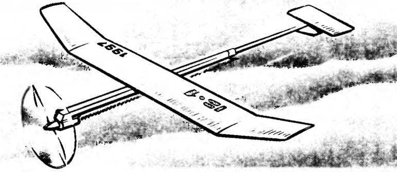
 Proponents of class rezinomotornaya expense of building a traditional model B1, do not turn the page of the magazine, seeing the drawings of equipment, by the external signs relating to the child “schematical”! Overcome the neglect of long ago you passed the scheme and read the material. You may find many interesting things.