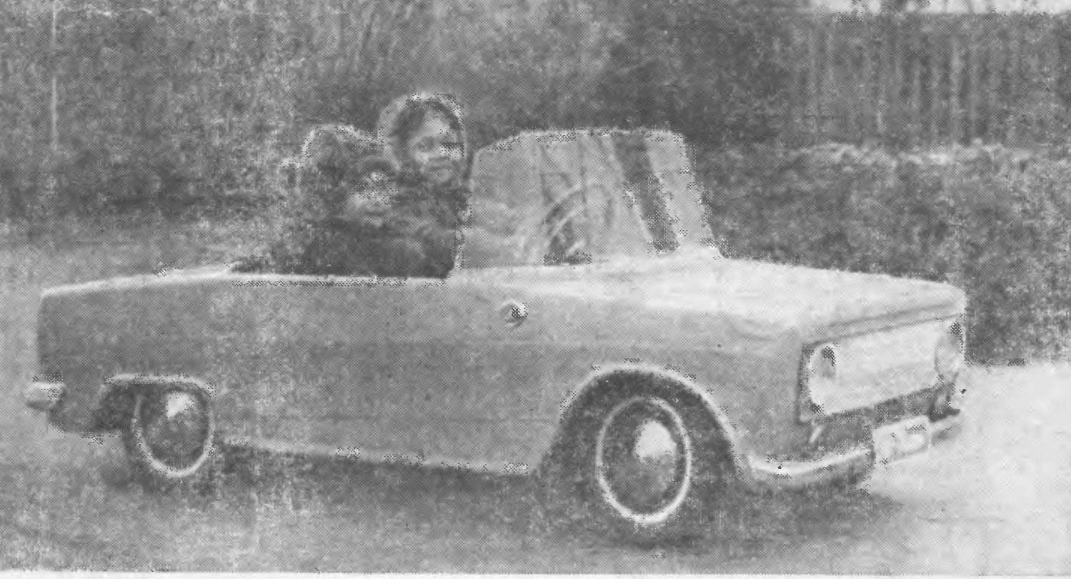
 “Oriole” — so I called built for the son of the electric car. The design idea came to me about two years ago, and much credit for this journal “modelist-Konstruktor”. Several months of estimates, calculations, dozens of layouts, hundreds of paintings and drawings of the body has led in the end to be quite rational, in my opinion, the solution. In the process of development of electric vehicles important issue was the problem of using abundant materials, parts and components, and as it seems, I managed to solve it.
BODY “Orioles” laminated of fiberglass and epoxy resin. There is no special need to describe in detail the technology you-gluing, it should be quite familiar to readers of “M-K”. It is, perhaps, to dwell only on the method of making a “fool”. Its basis is a wooden frame, nailed together from discarded material — strips, boards, plywood, cardboard. Final form is obtained by alignment of the clay. The final operation is pasting “fool” newsprint on silicate glue.
After the putty irregularities, dents, the body is treated with sandpaper and polished.
To facilitate access to the battery and other components of the electric vehicle, front and rear body covers are equipped with “bonnet” and “boot”.
WHEEL of machines are made with the tires from the wheels of a scooter. For disks it came the caps from the pots, connected by a spacer bushings and hubs. Within each hub pressed two bearing N203. For wheel covers used lids from milk cans.
The difference of the rear wheels only in the fact that their hubs do not have bearings.
FRAME “Orioles” is welded from steel channel and 20X10 mm is a spatial structure, which in conjunction with a fiberglass body has sufficient rigidity and strength.
The front axle consists of the bar, two rocking chairs and two axles. Depreciation is carried out using two springs in a cylindrical glasses.
Rear axle is a frame placed on it two bearing assemblies, motor and gearbox. To lower revs it came gear from the old electric drill, its the gear ratio and 23.7.
The electric car includes a DC motor 400W, its working tension 24 V, but it works well and at a voltage of 12 V. power Source are two batteries with a voltage of 12 V each; they are assembled from elements of NC-55.

Fig. 1. Four projection “Orioles”.

Fig. 2. Frame “Orioles” spatial welded construction.

Fig. 3. Steering column:
1 — ring 2 — button signal, 3 — lock nut 4 — washer 5 — washer 6 — spacer, 7 — pin, 8 — column, 9 — cable drum.

Fig. 4. Front axle:
1 — knuckles, 2 — stop, 3 — traverse 4 — axle shaft-rocker, 5 — Cup with a spring shock.

Fig. 5. Details of the front suspension:
1 — traverse, 2 — stop, 3 — rod of a steering trapeze, 4 — axle shaft-rocker, 5 — knuckle with axle (right).
Via switch B6 battery can be connected in series or parallel. In the first case, a battery with a capacity of 110 Ah with a voltage of 12 V. This battery is good because it can withstand the large inrush currents that occur when starting off. In the second case, the battery capacity of 55 Ah with a voltage of 24 V. This switch position corresponds to the second speed of the electric vehicle. The third position of the switch Q6 closes the supply circuit of the engine.
Reversal of the motor is controlled by switch Q1. It has three positions, the first and the third correspond to the positions of the “forward” and “back”. Switching V1 into the position “back” light up the brake lights lamp L2 and LZ.
The Kh1 button is interlocked with the foot brake. When you press the pedal past the lamp L1 in the driver’s cab and the lamp L2 and LZ (brake lights). For switching lights (lamps L4 and L5) serves as the switch B2, and the front and rear position lamps (L6, L7 and L8, L9) — VZ and V4. Relay runs turn the main switch Q5, when activated light up flashing light bulb 10 and 11 or depending on the position of the switch 10 and L12 (L-10 — indicator light “flasher” lamps located in the cabin).
The sound of the motorcycle is switched on with button Кн2 located on the steering wheel.
On the dashboard of the car mounted ammeter with a scale 30 and a voltmeter with a scale of 30 to monitor battery voltage and current.
The scheme provides protection of the motor and batteries from short circuit and overload with automatic circuit breaker AZS-20. The only disadvantage of its use — you have to hold the hand switch of the machine in the beginning of the movement so that it is not knocked in-rush current. Automatic triggers in the case when the electric vehicle hits an obstacle or when you switch the toggle switch to reverse the motor.

Fig. 6. Rear axle:
1 — frame, 2 — rail, 3 — leading the drive axle, 4 — bearing cap; 5 — bearing housing, 6 — washer 7 — bearing, 8 — nut, 9 — Cam coupler, 10 — gearbox, 11 — finger clutch, 12 — bolt engine mounts. 13 — motor, 14 — bolt M5, 15 — shaft, 16 — bearing cover, 17 — fastening strap.

Fig. 7. Rear axle details:
1 — frame, 2 — bearing housing

Fig. 8. Wheel electric vehicle:
1 — rubber band 2 — bolt М6Х30 mm, 3 — bearing, 4 — puck, 5 — bolt shaped M5, 6 — nut, 7 — bearing cover, 8 — cover, 9 — washer 10 — nut M6 11 — spacer. 12 — the case of bearings, 13 — tensioning bolt 14 drives the wheels.

Fig. 9. Wiring diagram “Orioles”.
Switches B1 and B6 adapted from standard switches to remote control. As shown by long-term operation “Orioles”, they are quite reliable: burning of the contacts was observed. On the dashboard of the car and the cabin are mounted ammeter, voltmeter, toggle the inclusion of turn indicators, headlights, warning lamps turn signal and brake switch reverse the engine, brake pedal, shifter and radio.
Seat double, is a wooden frame covered with foam and leatherette.
Front grille “Orioles” made of light-diffusing fluorescent fittings fluorescent lamps. The windscreen is arched pattern of Plexiglas, heated over the gas stove.
As the test showed, and they were very hard, the car was very “tenacious”. My son used it for trips to visit my grandfather who lives in a nearby village (the trip is about 18 miles), and reserve when fully charged battery was sufficient. Practical speed of 5-6 km/h and 18 to 20 km/h respectively when the first and second positions of the switch Q6.
V. VOLOSHIN


