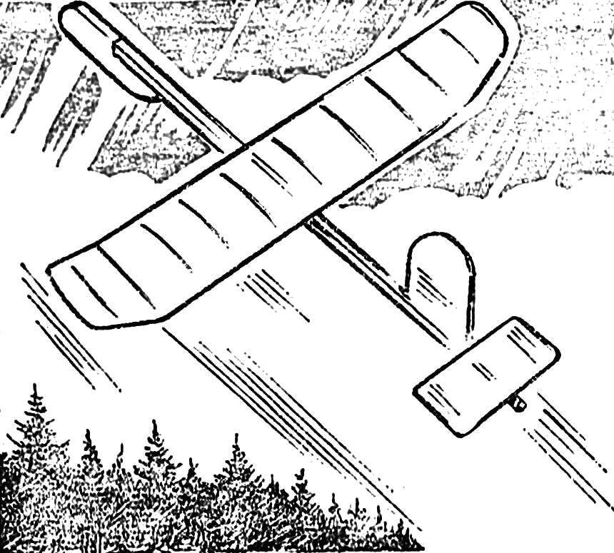
We offer a simple glider is designed for young athletes, students 4-5 classes. The model is simple to manufacture, does not contain elements from scarce materials and can be recommended for “small batch production” in all circles of the cart.
The basis of the fuselage is pine or fir rake section 9X10 mm and a length of 900 mm. cross-Section from the middle to the tail is useful to reduce to 4X5 mm. in Front podklyuchaetsya the shipment of a wooden plate the size of 20X40X150 mm., the keel is bent from aluminum wire, Ø 2-2. 5 mm, the ends of the workpiece is flattened and primatyvajutsja to the rail of the fuselage thread with glue; with the keel mounted stabilizer, the contour of which is formed by the rods cross-section 3X3 mm (edges) and the aluminum wire endings. The Central rib of the stabilizer, a wooden plate with a thickness of 3 mm.
Schematic model of the airframe:
1 — cargo, 2 — rake of the fuselage, 3 — keel, 4 — stabilizer, 5 — “ear” wing, 6 — wing.
The site of the junction of the center section and “abalone”:
1 — the edge of the center section, 2 — wire rib transfer, 3 — “area”, 4 — flange “ear”.
The main part of the wing — power of the edge section 4,5X4,5 mm. Planed they should be of specially selected grained wood. Rib strips of 2X2 mm. After grinding the sawed workpieces are placed for 5-10 minutes in hot water then clamped for molding the device, consisting of a base (metal sheet 180X200 mm with a thickness of 1-1,5 mm) and clamping the metal bars. After drying on a closed hot plate and cooling rack space in length, is removed from the device and cut. Round off the ends neatly so they are easily included in a pre-drilled in the edges of the hole. Assembly is glue.
Stabilizer:
1 — wire ending, 2 — edge, 3 — the Central rib (profile PLANO-convex).
Wing tip:
1 — wire ending, 2 — edge, 3 — plain wooden rib.
Device for forming of the ribs:
1 — bent leaf base, 2 — bars clamping of workpieces rib, 3 — rib billet, 4 — line marking cutting workpieces to length, 5 — screws.
Of the fixing Assembly of the wing to the fuselage:
1. fuselage, 2 — “stand”, 3 — bar for mounting hooks, 4 hook (steel wire Ø 1,5 mm), 5 — edge of the wing, 6 — bar that defines the installation angle of attack.
The finished center section with “corners” of the flattened and bent at a predetermined angle aluminum wire podstegivaet details “ears”. The rib at the transition can be both wooden and wire. Ending by construction absolutely the same as on the stabilizer. Mounted the wing a fuselage using the “stand” section of 8X10 mm and a length of about 190 mm Under the front edge of the center section to put the block 8Х10Х15 mm — this will provide the required angle of attack. The wing details secure them with thread and glue, and entire Assembly is permanently fixed to the fuselage only after debugging of the flight model.
The drawings indicate the size increased modification of the airframe. From the suggested it has a more powerful edge of the wing (5X5 mm) and stabilizer bar (4X4 mm), and the presence of two intermediate ribs in the set of stabilizer. The angle of attack is also specified lining under the front edge of the bar with a height of 7 mm. the Flight characteristics of both models are approximately equal. When tightened to 40 m Leer time cladding in windy weather from 60 to 80 C.
V. SMIRNOV, the head of the circle, p. Talovaya, the Voronezh region.
Recommend to read SANI — FORWARD! In his letter to the editor a resident of the village of Blagoveschenka of Altai Krai V. N. Ermakov calls himself a regular and faithful reader of our magazine. However, Viktor's being... WHAT IS BLINKING ON THE TREE? Among the variety of flashing Christmas lights increasingly popular get the "ultra simple", consisting... only of the LEDs. Instead of the usual piles of circuit design (with electronic...  We offer a simple glider is designed for young athletes, students 4-5 classes. The model is simple to manufacture, does not contain elements from scarce materials and can be recommended for “small batch production” in all circles of the cart.
