1 — ending (pine 4 mm thick), 2 — solid side rail (pine 5×12 mm), 3 — auxiliary stringer (pine 2×4 mm, that is for the reliability of the connection of the ribs with the forehead of the wing), 4 — front edge pine (5×5 mm), 5 filler head (foam packing or PS-4-40; is processed according to the profile by cutting armostrong templates), 6 — power skin of the forehead (Whatman epoxy resin; the rear portion of the monolithic spar not paste), 7 — gain (fake plate)8 to the Central power rib (lip 8 mm thick; to put to the skin of the forehead by Whatman), 9 — Central rib (material similar parts 10), 10 intermediate ribs (foam PS-4-40 or PVC trim fake veneer thickness 1.5—2 mm), the 11 trailing edge pine (3×5 mm), 12 — reinforcements rear edge of the pine (1,5×5 mm), 13 — rib transition (material similar parts 10). The grooves for the hemispherical protrusions of the cradle to perform in the markup after finishing the wing. At the site of attachment of the brace to provide end-to-end boss of a dense wood.
Stabilizer:
1 — ending (pine 4×4 mm), 2 — trailing edge pine (2×4 mm), 3 — filler (foam packaging, or grade SS-4-40), 4 — the growing edge (a pine 4×4 mm), 5 — of the Central rib (pine 4х12 mm), 6 — the leading edge pine (4×4 mm), 7 — a covering (writing paper epoxy resin).
An airfoil (M1:1):
A — the main variant, B — variant with ribs cut out of plywood with a thickness of 1,5 mm, In — zernoproduktovy the option of covering a thin piece of paper on epoxy resin.
The top longeron of the fuselage is absolutely straight, which makes it easy to control the correct installation of all parts timemay. After sticking to the upper spar foam sections with the thickness of 22 mm (which corresponds to the width of the future of the fuselage) and the front of the boss of lime well dried, the node is pressed against a flat Board-the slipway and with the help of the planer and the bars with sandpaper is processed bottom surface. Without removing the workpiece from the pile, glued the lower spar (in the rear panel spars should converge together as shown in the figures). Do note that the fuselage Assembly is not only suitable epoxy, traditional binders in model aircraft but also casein glues, including clerical grade.
After drying and removing from the pile the fuselage carefully vyshkurivaetsya and on the sides of the sheathed paper. The technology of this operation is as follows. Initially, the paper sized with the stock from the side, glue to the fuselage, is covered with a light layer of liquid Amalita. Waiting for complete drying, the same surface is applied svezhenakleennyh epoxy resin at the rate of about 0.3—0.5 g/DM2 , disperse it with a rubber spatula and using a thick plywood lining is pressed against the drawing paper to the Board are placed on the slipway of the fuselage (by the way, here you will appreciate the fact that the side faces are also straight). Similarly, or simultaneously sheathe and another Board.
Thus come with the filler cut out of foam stamps of PS-4-40, or mild, grade PVC. In the case of lightweight foams from packaging should not only immediately give the most accurate workpiece shape during cutting armostrong (to avoid the necessity of further treatment], but paper and glue for a different technology. The fact that melkosortnyj packaging foam needs a more powerful reinforcement of the surface, so the paper is not primed Americom to close the pores and reduce the resin, but rather seek to maximize saturation of the paper “epoxy”. For this resin after mixing optionally diluting with ethanol until the density of vegetable oil and put on paper. Waiting for the absorption of the resin, of the protecting strip of the Mylar film and the “sandwich” kiss with a smooth lining to the Board.
Completion of the heads of the M3 screws mounting the engine on the parts of the motor.
Changing the installation angle of the stabilizer in the transition from a PLANO-convex classical profiling to profile a “flat plate” (or symmetric).
In the diagram below: α° — the angle of zero lift (for a thin PLANO-convex profiles are 1 — 3° depending on the shape of the spout and the relative thickness of the profile). To create an equivalent aerodynamic effect plate must be set at the same angle as the line is α° PLANO-convex profile.
Fuel tank-timer:
1 — supply pipe, 2 — account the volume of the tank (exact size to pick up during test runs with specific sample engine, ensuring the operation time of motor at 0.5 s lower than the maximum allowed), 3 — connecting tube, 4 — the main volume of the tank, 5 — outlet window.
A — the horizontal position of the model when you run or debug engine, B — position climb (immediately after the lifting of the nose of the model cut of the connecting pipe exposed, the excess fuel is merge from the main volume, and the engine is operating at a calibrated volume of fuel).
In both cases, the casing and the fill material is the fuselage after the production is further trimmed, glued macalintal paper and varnished (the layer of epoxy resin allows not to be afraid of the dissolution of the foam components nitrobarite). In the bow longitudinal propyl runs exactly on the axis of the fuselage and the wing pylon is glued, cut from plywood in the thickness of 4-5 mm. Holes for screws M3 fixing motor engine are drilled on the place, and their inner surfaces are protected (protection of fuel) a layer of liquid epoxy resin. At the top of the pylon it is useful to glue the wedge-shaped part of the cradle. In addition, you need to mount the bamboo pins under the rubber band wing mounting (the cross section of the pin is elliptical, not too slack “shirt” plywood pylon) and boarding the plane to seal two semi-spherical protrusion that will make the precision of mounting the wing high and unambiguous.
Empennage the processing logic meets the fuselage. Keel after pasting the writing paper and the coating is glued in the fuselage at the same time tightly with a wire crutch, a stabilizer for protecting crop model. For precision mounting of the keel should be treated very carefully — even at small deviations from neutral during overflights Tierney most likely you will need to tin the trimmers.
Split a “breaking” strut of the wing:
power parts symmetrical about mid-length of brace (D16T secheniem 2×10 mm); when building in the wells zamatyvaetsya thin cotton thread 5-8 coils, the ends of which are filled on site with glue.
The stabilizer is similar in design, is mounted on the fuselage according to the classical scheme (a rubber ring with a draw the tail of the stabilizer), but without a wick device. Of course, to put it easy, waiting sverhdorogih conditions at the start may force you to go for it. But… there’s still time — not a glider, and leaving her in the powerful thermals can be counted on the fingers. For the simplified models is very little really; Yes, if that happens, in the end, simple timesnow not as pathetic as promised. But cases of breakdowns and failures relating to the wick device, much more than I would like. The simplest approximate calculation of the reliability of start (correlated with the ease of use, the model and all the number of knots) “school” Tierney clearly favors rejection of a wick device.
So, to put a wick device or not, you decide for yourself. We want to note one important feature of the horizontal tail with the profile of the “flat plate”. It’s different, unusual angles of degradation (the so-called difference in the installation angles of the wing and stabilizer). The fact that in contrast to the classical stabilizers with PLANO-convex profile of the desired Aero-dynamic effect is achieved at blackplatinum at other high angles of attack. This means that in our model the installation angle of the stabilizer may be longer than the wing! In such a situation you need to be ready at the beginning of the trial runs. By the way, we will be even more reliable in the manufacture of the model to set the mounting angle of the horizontal tail is exactly equal to the wing and debug to start in this situation. Here are two possibilities: first, when the engine is left without Vicosa down, and the wing and stabilizer are at an angle of 1-1,5°, and the second when the supporting surface of the model are at zero angle, and the axis of the motor shaft is rejected down at the same angle.
The new wing model is designed specifically for the conditions of its production beginners. Because of this, in the main embodiment of the ribs is made of foam with slatted edges. You say it’s hard! Not if you consider that rib when the proposed technologies are “stack” — or rather in a single block. This means that after sticking to a flat plate veneer billets of foam and further pasting it sorgu steaming plate of the same veneer you will only have to saw the dried unit billet to a lot of great ribs!
Otherwise, already acquainted with the technology perabumulih of items you probably already have become clear, and additional explanations on the wing is not required. The only thing I would like to note — we recommend you build the wing separately conduct, on the nose and tail on finished parts before it will snap the auxiliary stringers, and join them only at the final stage of Assembly on the slipway. When the marking of the forehead with a paper on the epoxy the wing can be sheathed as mcalenney paper and Mylar film.
The basic data model
Wing area, DM2 : 18
The surface of the stabilizer, DM2 : 4,2
Carrier total floor area, DM2: 22,2
The mass of the model, g: 450
Specific load, g/DM2: 20,3
The propeller (diameter*pitch) mm: 165х110
Balancing these models
The efficiency ratio of stabilizer: 1,13
Critical alignment, % SI: 83-85
Alignment models, % SI: 78-80
Wing setting angle, deg: +1
The installation angle of the stabilizer, deg: +1
Twist wing (right-Central part to the “eye” at front edge) mm: +2
Turn on takeoff: right
Turn planning: right
Adjustment mode off — use the axis of the engine up to a small deviation to the left.
Adjustment of the planning regime change in the angle of installation of the stabilizer and its inclination.
The time required for each circle at a steady state of planning for 25-30 seconds.
R asososca the elements of the model, g
Wing: 120
Stabilizer: 18
Motor tank, engine mount and propeller: 185
Reload to the desired weight: 15
V. VIKTOROV, head of the society
Recommend to read VEGETABLE “KINDERGARTEN” Very often spring in Siberia turns out to be prolonged and cold. That's why most gardeners are in no hurry to plant seedlings of the most common vegetable crops—cucumbers and tomatoes—in... FIGHTING A MIRAGE Fighter-interceptor, the Mirage IIIC. In 1953, the French air force announced a competition to create a light supersonic fighter-interceptor. Virtually all aircraft manufacturers and... 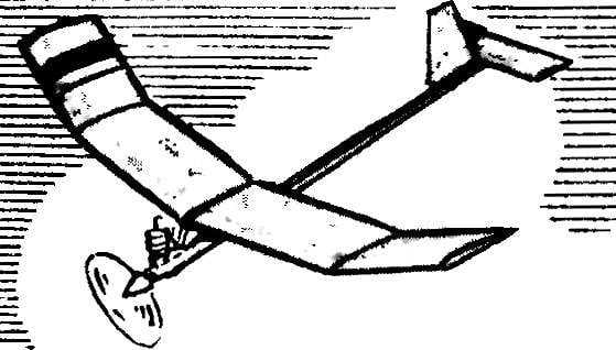
 When designing equipment for the new sports season to our members once again raised the question of finding a middle ground between championship superparty and sverhpredelna models for beginners.