R and S. 6. The tail part of the fuselage:
1 — trim the tail boom (I mm plywood on both sides), 2 — tail boom (selected straight grained pine 6 X 6 mm; by the end of the cross-section uniformly along the beam length to reduce to 3.5 X 3.5 mm), 3 — the elements of the border of the keel (pine 1,5X2,5 mm; before gluing the strips to steam), 4 — filler plate keel (packing foam thickness 2.5 mm), 5 — the root of the keel edging (pine 1.5 X x2,5mm; required for mounting separately, izgotovlenie keel on the tail boom of the fuselage) .
Fig. 7. The site of attachment of the tail boom:
1 — pipe of the engine fuselage, 2 — rear insert motor part, 3 — boss-perehodit (team detail three fake plates with spacers of mm plywood; the center plate must be calibrated in thickness in strict accordance with the overall width of the tail boom with lining; after the Assembly and control of detail is handled on a lathe with front), 4 — the emphasis for fixing the beam vaccinatum position (0.8 mm aluminum), 5 — loop hinges of the beam (made of anodized aluminum; when mounted on the beam by means of threads with epoxy glue to the wrapped area of the beam to Shine the material under the thread size 0.4 mm), 6 — tail boom with lining, 7 — thread fixation of the beam in the working position, 8 — wick of determinator, 9 — forked pylon to install perejaume thread wick (aluminum), 10 — tail boom, 11 — axis of the sample beam (OVS wire diameter 1,5 mm), 12 — spring is a translation of the beam in tilted position (OVS wire diameter 0.5 mm), 13 — the screw of adjustment of the beam in the working position.
R and p. 8. The hitch mechanism of the propeller with automatic change of the step. The following is the condition for the free folding of the blade depending on the cross pipe of the engine fuselage DF.
R and p. 9. Device stop folding propeller:
1 — the system of the propeller with a counterweight, 2 front boss fairing, 3 — motor chimney of the fuselage, a 4 — pin device (OVS wire 0 1.5 mm; details of adjustment, see text).
Fig.10. Fixtures for the manufacture of finished workpieces:
1 — base (Lipa; upper surface profilerate in exact conformity with the lower arc of the wing profile), 2 — tape-Scotch for fixing veneer of 3 — the bottom casing ribs (Linden or aspen veneer with thickness of 0.7 mm; the dashed line shows the boundary of the working area; Skoch attaches the veneer for technological allowances), 4 — stocking filler ribs (packing foam, cut the wing profile according to the thickness of the skins and with an allowance in the tail area), 5 — seat mounting dural invoice templates for дообработкb foam filler ribs; additionally, to provide space for the centering pins 0 2 mm).
The next operation is gluing the top sheet of veneer, pre-calibrated in thickness and lightly lacquered with hand gluing. To clamp this cladding is better to use additional strips of tape-Skoch and cargo. The obtained preform for a rib cut along the length of the profile in the pre-applied markup, and then dissolve into individual ribs on vibrolance, on the desktop, the simplest of which is fixed guides.
The weight of one such rib thickness of 2 mm is not more than 0.3 g. Compare with slatted ribs from “schematicity” that weigh about 0.8 When using lightweight aspen or spruce for veneer edging mass “sandwich” part is in the range of 0.2—0.26 g with a very high strength and stiffness. By the way, the weak balsa ribs with a thickness of 1.5 mm at the airfoil would have a mass of 0.11 g.
For information useful to cite one size: total weight of all finished parts to the wing of the new model (extremely stiff in torsion and enough .solid) is equal to 13 g.
Similar technologies are prepared and spouts ribs, and oblique polonaruwa. With streamlined production in many parts is very fast and without marriage, which is especially valuable in the construction of multiple models at the same time and in the conditions of model aircraft clubs. The groove under the mine spar in the ribs cut chip razor blades on overhead metal templates.
The only “downside” of the proposed methodology is the inability to use as a covering for the wing macalintal paper on Amalia (or the operation should be performed very carefully and slowly, carefully drying each new layer of varnish, as nitrobacteria and a pair of lead light packing foam into complete disrepair). However, in our opinion, this makes no difference — better stitched from the rough filled with Dacron nothing. But this material is quite widespread today and is even less scarce than micuenta paper or a good enamel.
The longitudinal elements of the set of the wing are made of dense meltology pine or spruce. Their weight: leading edge — 5 g, the rear edge is 5 g (ponytails straight ribs hit the edge of 1-1,5 mm), spar — 5, by the Way—^ to use monoblastny spar we went deliberately, knowing that the Flexural allowable stresses for wood and a half times more than the compression Dvupolnoj scheme with the wall. In addition, when a diagonal diagram of a set of cross wing, you can count on the formation of edges and longitudinal rigid three-dimensional triangular structures-“beam”.
Wing Assembly is conducted only on plasticized epoxy resin by impregnation in the dry seams assembled on the staple frame. Very preferably the formation of resin fillets at the junctions of the front edges of the ribs and trailing edge. In ready frames dominiruyut missing pieces (scarves, ending, strengthen and trim the ends of the ribs of the connectors). After complete curing of the binder frame, of necessity, cleaned, optionally increasing the longitudinal dummy pads to the height of the profile ( we believe it is excessive) and then fit the wing elements is filled with rough Dacron with a thickness of about 0,015 mm. Adhesive required for this operation, or divorced-or BF-2. The weight of the finished wing with the hinge pins of the detachable “ears” is in the range of 40 g. of Course, to make such a wing is even easier due to the weakening of its individual parts, but the stocks weight in the proposed model is very high, and loosen the wing is just pointless.
The stabilizer is designed for new-fangled scheme — profile “flat plate”. The design of this item is completely understandable from the drawings. Note that assembling it is also carried out on epoxy resin. Weight of finished stabilizer with no skin — no more than 4 g. If you have a wide Syrian Skoch (he went to the office supply stores and was in rolls of a width of 60 mm, translucent, beige) — consider yourself lucky. If fitting a surface stabilizer such skochem with a light heated the iron on the creases of the skin, get the perfect piece for almost the same mass. It is also good to use sticky Mylar covers for books. Last only much harder as glued to the foam, and edging strips of the stabilizer — it is important to choose the temperature of the iron. In any case, when the plating film weight of the horizontal tail does not exceed 5 g. once again Compare the proposed design with the “schematic”, where a rack and pinion stabilizer weighed 11 g.
On the engine part of the fuselage, we used a similar cardboard material, however, is more technical, more durable. This is Kraft paper. Tape from it without problems is wound on the disc with an interference fit, epoxy resin, and the thickness of the pipe gives a stronger and more results compared to cardboard. In addition, eliminates the problem of seam and Stripping ledges formed by the large source material.
Absolutely original, we managed to fix a node of articulation of the tail boom ‘ is a motor part. At first glance it looks a bit complicated, but… think about how much weight we managed to remove at the expense of losing site of the whole control system and drive mechanics of its permutations and you will realize the win-win of the new solution. Due to the sharp relief of the rear fuselage the size of our shoulders rezinomotornaya approaching championship standards! Maybe you will be lucky to find a more simple solution to the “breaking” of the fuselage; we only advise in any case the maximum attention should be paid to the rigidity and absence of backlash in the connection of the motor part with the tail boom in flight mode (after actuation of determinator do not care).
The wing pylon is solid, lightweight aspen. In place it is glued before painting and varnishing motor pipe, after approximate alignment of stocked models. Note that in the normal mounting of the wing rubber band in our design has an important addition: the tabs on the cradle and the corresponding hemispherical depressions on the Central rib of the wing, which provide an unambiguous position of the bearing planes even with a sloppy build models at the event.
Regarding the propeller we have no specific recommendations are not going to give. After all, in every circle of aircraft modeling on this issue developed their own approaches, and challenge them we are not going. We note only that for the transfer of any two-bladed propeller in a geometrically similar single blade need to use magnification all sizes equal to 1.15. Then retain the character of the unwinding of a rubber tourniquet and the operation time of the rubber motor. We will talk about something else — about the mechanism of folding stop screw.
Typically, this mechanism is always given a lot of attention and… the Junior it rarely works in accordance with the wishes. We propose to abolish the mechanism generally in favor of one simple pin protruding forward from the tip of the motor part of the fuselage. His task in the following. When the rubber motor will completely run out of energy and torque is not to be missed for the rotation of the propeller, then (and only then, what the proposed scheme is clearly profitable, well-known machines!) under the action of the spring folding drive rotation of the blade with the balancer will start to warp. When the angle of skew 45е wire around the butt of the blade faces on said pin, the screw is completely stopped and then finally folds. The skew angle at which the contact with the pin, must be clearly less than the angle at which the blade touches the wing, then the reliability of the proposed scheme will be absolute! It is also necessary to find by experiment the position of the pin around the circumference near the bottom of the diameter of the fuselage. With regard to the need in the spring of the folding propeller shown in the drawings, note that in the end we refused. The process of folding now is not as intense, but softer and final setting of the blades along the fuselage. Indeed, as mentioned in an earlier article, the weight of the moment from the asymmetrical suspension of the biscuit on the shaft enough to clear the retaining screw close to the fuselage.
In conclusion, I must say that the proposed model after the final Assembly and weighing had to to fetch the required values, since the total mass was found to be only 95 grams without rubber motor. So if you want there is an opportunity to strengthen some of the nodes. We such need is not found in the proposed new rezinomotornaya class B1 is clearly stronger and resursnie other well-known structures and never let our juniors. Flight capabilities of such a machine is very high, however, as in all other expense of building a traditional school, here equivalent with the technique is the ability of an athlete to debug it and properly oriented in terms of competition.
V. SHUMEEV, the head of a circle of aircraft modeling sport
Recommend to read VOLTAGE CONVERTER FOR MS Designing electronic devices on integrated circuits, radio Amateurs often use to display the information indicators IN gas-1 — IN-16. They usually feed from the mains AC voltage of 220 V... THE SECOND “HEART” ROUTE Most often the chassis of modern highway car made of metal. In the case are tinplate, thin sheet duralumin and brass, steel wire. Requirements and the chassis is presented are many, and... 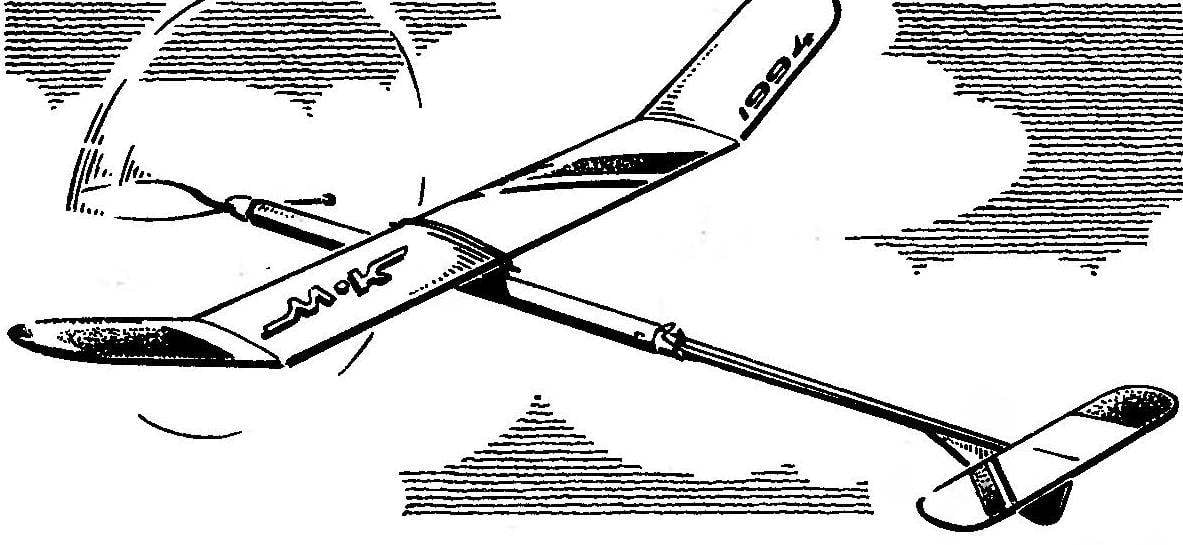
 The magazine “M-K” in the last few years has published a number of interesting patterns with rubber motor, with an unusual decision nodes, and technological methods of their creation. Let “garbage weed” from their schemes, to design, we think, a very good and promising machine of the class B1, which combines not only good flight and operational characteristics, but also the manufacturability at a maximum nedvizimosti raw materials.