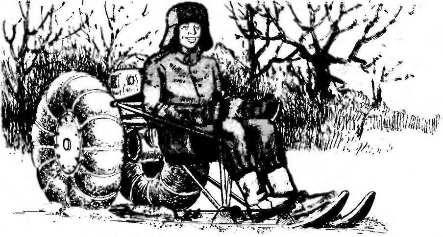
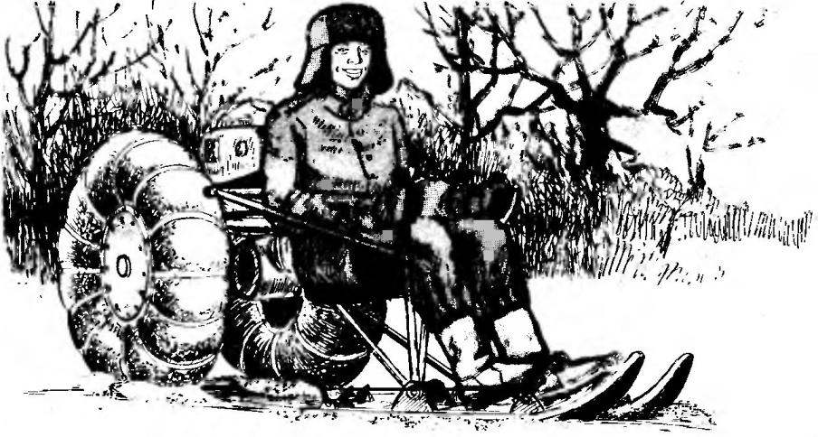
We offer our readers a small wheel-ski snowmobile—simple, unpretentious, simple to manufacture and inexpensive to operate. This car, dubbed the “Penguin” is a vehicle of an articulated scheme, which allows the rear wheels to navigate through the compacted skiing track when driving straight and in turns. The name “Penguin” . got in the way of movement, similar to the approach used by these birds, which placed a chest on the snow and pushing with the legs, very quickly slide forward.
Snowmobiles equipped with an engine type V-50 (these were used on mopeds “Riga” or “Carpathian”) and can reach the speed of 40 km/h.
The basis of the “Penguin” is the tubular frame which consists of two parts (half-frames), connected by vertical hinge. The rear frame are mounted the engine, fuel tank and rear axle with a pair of pneumatosis low pressure. On the front of the half-frame supported on two skis, mounted the driver’s seat and set the controls of the snowmobile — levers directional control lever clutch, crank the throttle of the carburettor (“gas”), handle gear shift and pedal brakes pin type.
The design of the snowmobile, it is desirable to start with the selection of pneumatic chambers for wheels — their size will depend on the geometrical parameters of the frame. The optimum diameter of the pneumatic chambers in an inflated state is about 550 mm. However, the fit of the camera and larger size will need to increase the length of the struts connecting the hinges ski with front polurama, and replace the sprocket on the shaft of the rear wheels to the other, with a large number of teeth — this will allow the engine to run normally.
Snowmobile “Penguin”:
1 — the brake pedal; 2 — step; 3 — ski; 4 — thrust braking device; 5 — pin brake device; 6 — a lever-yoke pin drive; 7 — exhaust pipe; 8 — the engine-50; 9 — exhaust muffler; 10 — sprocket chain drive; 11 — colesevelam; 12 — chain drive; 13 — tank; 14 — back seat driver; 15 pull the steering device; 16 — frame front; 17 — seat; 18 — handle of the throttle of the carburettor (right); 19 — clutch lever (left); 20 — lever steering gear.
Wheel (straps on the side view is not shown):
1 —strap nylon; 2— nut M10; 3 — pneumatic chamber; 4 — stud M10; 5 — disc (plywood s8); 6 — Bush Central; 7 — flange; 8 — a bolt of M6 with nut.
The trajectory of the snowmobiles in turn (it is seen that the drive wheels move on the compacted skiing track).
The rear frame of the snowmobile — spinal type. Its power is based on steel pipe diameter 34×2,5 mm, which is welded to the front and rear attachment points of the engine, the bearing of the rear axle and steering column. Knots engine mounts are welded in place: first, the clamping units are cut from steel sheet of thickness 2.5 mm, then the bolts and nuts with thread M8 are secured to respective nodes of the motor, then the engine together with the mounting assemblies is fitted to the pipe frame. Further, the nodes primatyvajutsja to the frame by welding, the engine is dismantled from the frame, and the details are finally welded. To the spinal tube are welded and the traverse control, consisting of a tubular cross member and a pair of tubular braces, and mounting brackets fuel tank. The latest from moped “Karpaty”, but it would suit any other, even home-made, of plastic two-liter cans of motorcycle fuel tap with filter-sump.
The front frame of the snowmobile is also spinal, it consists of one tube diameter 40×2. 5 mm, bent in the form of letters, With the rear polurama it connects with a pair of bridges — parts, bent from steel sheet of thickness 2.5 mm, and the axis (bolt M12), passed through holes in the bridge and in the steering column rear semi-frame. On the front frame are also mounting brackets for seat and backrest. Themselves seat and back — suitable size of the chair.
The rear axle of the snowmobile is a bearing housing, machined from a steel pipe, which rotates on a pair of bearings intermediate the sleeve. Through the last skipped a tubular shaft, which is fixed to the clutch connecting shaft and the rear wheel, and a sprocket chain transmission. Note that the described design of the rear axle sealed — for homebrew to make this much easier. However, in the manufacturing process you need to follow a certain Assembly technique. First, through the spacer sleeve carries the rear axle and the connection is fixed “plug lap joint” (the so-called Union, in which one of the mating parts, the hole is drilled, after which it is sealed and melt firmly connects the parts). Further, in the bearing housing zapressovyvajutsja bearings and fixed to the spring split rings, and in the last turn on the shaft are fastened by welding the left sleeve and the Assembly consisting of sprockets, bushings and the right coupling.
Wheels the Penguin consists of a Central sleeve made out of cut steel pipe with a diameter 35×2,5 mm and two flanges of steel sheet of 3 mm thickness, a pair of plywood discs and twelve threaded studs with M10 nuts and washers. On the periphery of each of discs of plywood cut rectangular holes for mounting nylon straps, fixing the pneumatic chamber on the wheel. The wheel served longer, it is necessary to cover the plywood disks with hot linseed oil and after drying paint alkyd enamel. Please note that each flange is connected with a corresponding drive with only two bolts — one pair of holes for firm grip of the wheel with the shaft of the rear axle.
Each ski of the snowmobile is laminated of 5 mm plywood plates and strips of stainless steel (could also laminate, glass fiber or polyethylene); the total thickness of the ski is about 22 mm.
As a binder when gluing it is recommended to use epoxy resin. When viklane you should use the simplest slipway — hardwood timber or section of steel channel, to which the plywood plates were clamped using steel U-image-tions of the brackets are threaded at the free end and traverse wooden bars with a pair of holes in each. The bend of the sock is provided fixed on the slipway figural wooden bar, whose configuration corresponds to the profile of the front of the ski.
With the pivot bushings on the frame of the ski are connected with the base brackets, curved sheet steel with a thickness of 3 mm, and threaded rods M12.
The frame of the snowmobile:
1 — sprocket chain drive; 2 — the cheeks are the engine mounts and bearing Assembly rear axle; 3 — beam rear articulated (steel tube 34×2,5); 4 — small cheek (right and left) engine mounts and traverse control; 5 — beam control (steel pipe 22×2,5;) 6 — Klondike reinforcing; 7 — the case of a vertical hinge; 8,10 — bridges swivel device; 9 — brackets of the seat back of the driver; 11 — beam front half frames (steel tube 40×2,5); 12 — mounting brackets driver’s seat; 13,15 — struts ski bindings; 14 — bushing hinge; 16 — brace cross member (steel pipe 18×2,5); 17 — a plug yoke; 18 — rear axle shaft (steel pipe 30×3); 19,21 — couplings; 20 — the case of the bearing of the rear axle; 22 — bushing (caprolon, textolite); 23 — washer; 24 — the vertical axis of the hinge (bolt M12); 25 nut M12; 26 — pin connector (stub bolt M6); 27 — Bush couplings and gears; the 28 — bearing; 29 — lock washer, split; 30 — Bush staging.
Ski:
1 —shell rubber; 2— pedal brake device; and 3.21—washers; 4—step; 5-the screw of fastening of the footrest; 6–ski; 7 — a bolt with a nut attaching the main bracket skiing; 8 — bracket-ski, primary; 9 — the screw of fastening of podraza; 10 is undercut; 11 — pin brake device; 12 — grommet under the pin of the braking device; 13 — the lever-yoke; 14 — the lever of a drive of the braking device; 15 — return spring; 16 — a bolt and a nut of fastening of a bracket of a braking device; 17 — bushing levers brake device; 18 — pin M8 nuts; 19 — the axis of the rocker pair (M5 bolt); 20 — thrust of the brake device; 22,24— pins; 23 — a rod tip.
Ready for the ski is mounted the brake device pin type. It consists of two metal bushings, mounted in the rear part of the ski which can move freely steel pins connected by a pair of rocker levers. Last fixed by welding to the sleeve; the sleeve is welded and the drive lever of the braking device. Bushing with a threaded stud pivotally secured to the support bracket and provided with a return spring.
The force from the brake pedal located in front of the ski is transmitted to the drive lever through the tubular rod tips-joints at each end. The very same brake pedal bent from steel pipe with a diameter of 16 mm in the form of letters P; one end is stretched a piece of rubber hose, and the other inserted into the footrest, a bent sheet of steel 2.5 mm thick, and fixed there by a washer and cotter pin. Also splinted on the pedal and the tubular drive rod.
On the front skis are mounted and the levers of exchange rate management,which is pivotally mounted on the main brackets of the ski. The levers are made of steel pipes with a diameter of 22 mm, to one end of each welded hole with a diameter of 12 mm and the other side mounted gear motor and handle clutch (left lever). On the right is the lever arm of the throttle control of the carburettor (“gas”).
The levers connected to the traverse control using tubular rods At the joints of the forks of levers and yokes with forks on rods, control provided by so-called gimbal cross — intermediates with perpendicular holes for the axle (bolts). The use of frogs due to the fact that the control levers, linkage and cross member make complex spatial movement, respectively, and the joints shall be either gimbal or ball.
The engine is started using the starter cord for what the motor is removed the pedal kick-starter, and in its place installs machined aluminum pulley. Before you start the cord is wound on the pulley (three to four times), and then by pulling on the free end of the cord and is the start of the engine.
I. KARAMYSHEV
Recommend to read FROM “SPIDOLY” LAB! Instruments based on the radio. Determination of the frequency of an unmodulated source, an external signal. With the help of measuring GS you can configure any radio transmitting and... IT IS POSSIBLE AND WITHOUT GLUE Cracked plastic case compact vacuum cleaner "bumblebee" can be fixed without resorting to the traditional way of gluing. Enough to pull on the housing section of the camera motorcycle... Scroll back to top
 When winter comes and the snow is “fluffy blanket” covers the ground in many areas, the only vehicle able to overcome it “fluffy blanket”, it becomes tracked all-terrain vehicle or, more commonly, a tractor with a sled-scraper. Of course, you can buy a Japanese ski-goose-nicou Yamaha (though it is worth more than another car) or buy now rare a cheap domestic “Buran”. However, always need such a powerful machine?