
 This model can easily produce young technician familiar with the basics of automodelisme and able to work on machine tools. The construction should start with the manufacture of the pan, which is cast alluminium alloy or milled from a single piece of identical aluminum alloy. All marking and drilling the screw mounts and bearings rear axle is best to do when these details are ready. The tires are made of raw rubber by hot vulcanization and with a disk. In of front wheels chiseled the holes for the ball bearings 4Х16Х4, and the disks are pairwise connected by three M3 screws.
In the inner disks of the rear copes chiseled tapered holes, which tightly onto the cones of the rear axle, where the wheels, and the wheels with tires tightened nuts M5.
Of the engines offered “MK-16” or “Breeze.”
The flywheel for the engine is machined from steel, Art.3 and is mounted on the motor shaft using a split tapered bushing. Bevel gear, as a leading and led, made of steel grade 20X. Master and slave gear are, respectively, number of teeth: Z-20 and Z-32 (M1). The pinion with its flange is connected by screws M3 flywheel, and the driven is mounted on the rear axle and is fixed there with a pin. The rear axle is machined from steel khvg. It can be made also from silver steel. It should be subjected to heat treatment.
The front axle is made from spring steel 1-1. 5 mm, at the ends of its stronger axis, which are riveted and propisyvayutsya. In the centre is drilled a hole and radial slot for screws M4.
The fuel tank is made of tinplate. Baku is soldered to a stopping device consisting of a tap and wire rod. The tap is connected with the carburetor of the engine with vinyl chloride or polyethylene tubes with internal Ø 3 mm.
Cord strap is made from sheet duralumin brand D-16T with a thickness of 2-2,5 mm.
The body may be made of sheet aluminum or laminated fiberglass. Fastened to the pallet by means of a pin and screw (rear).
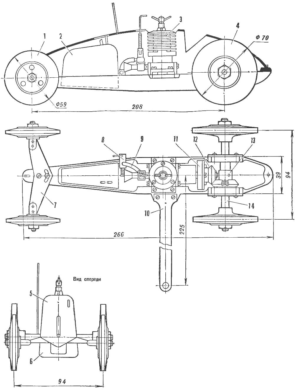
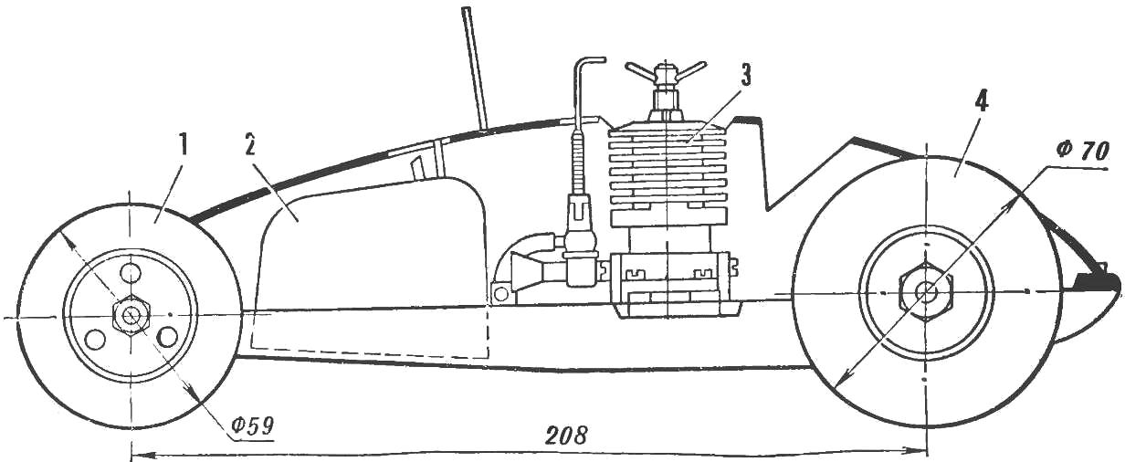
1 — front wheel; 2 — fuel tank); 3 — engine; 4 — wheel rear; 5 — body; 6 — frame; 7 — front axle; 8 — stopping device; 9 — fuel lines; 10 — cord strap; 11 — flywheel; 12 — pinion; 13 — the driven gear; 14 — rear axle.
The Assembly of the power plant model, it is better to: install rear axle driven gear and the bearing, it can mount the motor with the pinion gear installed. To find their relative positions when both gear will normally catch when rotating the rear axle. After this outline on the frame the attachment of the motor through its folders and then carefully drill four holes and cut thread M3.
Installation of front axle and cord trims is done on the screws in the places indicated on the drawing, and no difficulty.
Recommend to read
 ANYONE CAN MAKE AN AIRPLANE!
Having once decided to build an airplane, the home-made man is faced with a number of questions, and the outcome of the whole matter depends on the answer to them. It seems to me that... DIAGNOSTICS REMOTE
If not included home electronics, do not rush to carry the unit into the workshop — first is to test the functionality of the remote control (RCU). This can be done following simple way....
