Wing Assembly begins with the spar. The slipway will serve two flat Board, fastened at a right angle to form a corner. Both beam flange together with his wall. When the glue dries, one of the planks of the bench, place the drawing of the console in 1:1 scale. The pins fasten the front edge. Spreading the epoxy and using the same pins, place the lower part of the nose ribs and push him to the back of the spar. The upper are inserted, not yet hardened glue (it should be applied minimum number). A day later the frame is removed from the pile. Placed under the longitudinal Board thickness of 5 mm and the same way going to the back of the wing. Until the resin hardens, glue the two stringers.
After Stripping the console and fine-tuning the shape of the front and rear edges of the cut end-part — future “ears” and wire them to the Central part of the plywood (1 mm) plates from both sides of the wall of the spar. The ending (they are made from lime plate 4 mm thick) must be located above the slipway at a height of 100 mm. Note that before this operation it is necessary to adjust the length of the spar and stringers.
Assembly is under the tongue attaching the wing.
Now for the boxes — they will include language wing mounting. Each of them is made of two sheets of plywood 1 mm thick, between which the glued strip of the same thickness as the language, to 1.5 mm Ready box saw round, sanded and wrapped with thread and glue.
Stays put on the frame of the wing in the locations shown in the drawing, scarves of lime, 1.5 mm thick, embedding box and grinded root of the wing. It is covered long-fibre paper and covered with five layers of liquid Amalita.
Weight of the finished airframe the following elements: a fuselage with a language without reload of the nose 102 g, the wing 74 g, the stabilizer 7 g — a total of 183 g. it Remains stock in 37 g used to reload the bow. Recall that the weight of such models can not be less than 220 g! Taking into account that your scale can “ignore” 1-2 g, it is better to increase the weight up to 225 g.
ASSEMBLY begins with the fact that the language wing mounting podymaetsja in the drawing and is inserted into the cutout in the fuselage. Stabilizer tie box rubber thread covering the beam of the fuselage and the pin on the horizontal stab. Thread the pull pin fixing the wick. Attach both halves of the wing, and check its position relative to the stabilizer. “Ears” to screw over the stove, giving them a small negative angle (2 to 4 mm on the outer ends of the rear edges), check the angles of the wing (+3°) and horizontal tail (-0,5°), the position of the center of gravity (CG) of the model (68 mm behind the front edge of the wing). Screw starter hook to attach the stopper of the rudder and install the retaining screws M2.
The first flight only in the evening or in calm weather. And don’t forget to clip and light the wick! Even from ten meters of altitude your model, caught a sudden updraft, can go so far that you won’t be able to find her.
Adjustment begins with trial runs of your hand. Small shortcomings in planning can be corrected, selecting the angle of attack of the stabilizer. To do this, lay a plate thickness of 0.5 mm under the rear edge. Significant weaknesses it is better to compensate by changing the position of the CG. When finally the model will be good for planning, it is necessary to accurately determine the CG and drill in the fuselage a few holes Ø 3 mm (with a step of 6 PN) with the starting hook. First” Jack — in 5-6 mm in front of the CG.
As a rule, the model never has aerodynamic symmetry. It is detected on the first launches, the glider goes into specific only for this model turn. The selection of the rudder make sure the model was on the opposite circle. Such adjustment will help her better to stay in the narrow updrafts. The hook is screwed on the inner (relative to the center of the given curve) side of the fuselage. Just now try a puff on the guard rails with a length of 15 m. If the plane does not have random twists, the start takes place without difficulties up to the vertical position of the handrail. If is a marked tendency for the departure of the glider to the side, adjust the rudder. In extreme cases, move the hook one hole forward. With proper debugging in the final phase of the model is well dispersed that allows you to “throw” her on a trajectory upward spiral. Thus, when sufficient strength of the wings can score an additional 6 to 9 m height.
DMITRIYEV
Recommend to read
 VASE-IMPROMPTU
Now on sale a lot of different liquids, for example mineral water in large plastic bottles, including a beautiful corrugated walls not only round but also square shapes. If they do ask... ELECTRONIC IGNITION:OPTIONS
We are talking about different versions of electronic ignition devices (UEZ), is made as transistors and IC. The lack of scarce elements, as well as the simplicity of the schemes allow...
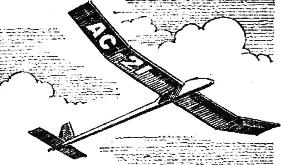
 The unusual design of bearing areas — that is the main distinguishing feature of the proposed model glider. Their advantage in ease of manufacture. The absence of cut from the sheet material of the ribs removes one of the major obstacles that usually stand in front of budding aeromodellers. Not once, not twice inexperienced hands of guys spoil tutu scarce mm plywood until it become satisfactory in quality ribs. And propilivanie grooves under the rail spars, stringers and edges too rarely at first. And the quality of the execution of this work depends on the strength, stiffness, and aerodynamic characteristics of the future model.