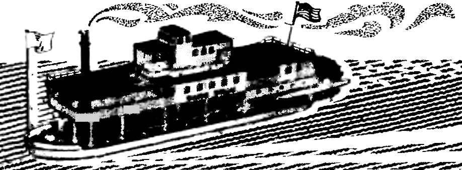
Even if the shoulder is already extensive experience in building boat-copies, still in the design of the new microtune he inevitably faces the problem of which engine to put in a future copy! Glow or compression — there are problems with fuel, sound attenuation, and vibration. Electric! But it is not without flaws, especially considering the large mass of electric accumulators.
Why not go for the most kalinaw way on the printout, for example, ships do not use real miniature steam engine! The attempt to realize this at first seemingly difficult ideas are brought very interesting results.
First of all about the engine (in a steam installation is the many large knots). It is easier to do from any of modelistica internal combustion engine a sufficient working volume. By the way, is well suited for these purposes, such a motor, as the Kometa MD-5, long-established in the normal glow performance as absolutely unworkable. For steam version it is better to make a new cylinder and perform only the outlet port to the vapor’s exit. By-pass (purge) the window is not needed — in their absence the crankcase of the motor will be closed, thereby maintaining during operation the volume of the crankcase sufficient oil.
The next stage of the work on steam power plants — production of two tanks: one for water and gasoline or another liquid fuel. The water tank is performed by the soldering of thick sheet brass or stainless steel with a minimum thickness of 0,8—1 mm (in the extreme case will fit thick roofing iron). The choice of material is due to the fact that the water tank is in the operation of the installation to be under the same pressure as the entire steam system. The fuel tank may not be as strong and shorter. Its dimensions are chosen in a practical way.
One of the most important components of installing a steam boiler. Its design is clear from the drawings, and the materials and manufacturing technology of the boiler elements each may choose according to their own wishes and possibilities.
Steam boiler:
1 — fuel feed pipe (copper Ø 3 mm), 2 — heat exchanger-evaporator, 3 — supply pipe of injector (copper, Ø 3 mm), 4 — tube steam extraction, 5 — evaporator water (tube Ø 3-4 mm), 6 — louvers for supplying air to the flame, 7 — nozzle, 8 — node mounting the nozzle 9, the lower chamber 10 is a pipe supply of water to the evaporator 11, the housing tube.
Heat exchanger — evaporator of the fuel can be made from copper box from the old barometer or in the form of a coil of thin copper tube. Tablewraplayout atomizer redesigns of toilet spray.
Steam valve, mounted in the engine head:
1 — pipe supplying steam from the boiler to the engine, 2 — brass valve body, 3 — spring 4 — ball-valve. The valve in the bottom of the piston engine have the center to mount the rod-pusher, which at the approach of the piston to the top dead point needs pressing the ball-valve up, letting thus another portion of steam under pressure.
Completion of the regular cylinder head of the engine.
Water tank:
1 — housing (roofing iron sheet or brass), 2 — filler neck (can be sealed), 3— valve (Schrader valve from a Bicycle or motorcycle), 4 — supply faucet valve.
Preparing for testing a steam engine is simple. In Carter converted the internal combustion engine pour engine oil in a regular diffuser carburetor insert plug (the oil should be replaced after approximately 50 hours of machine operation). Tanks are lled, respectively, with water (preferably distilled, to eliminate the formation of scale in the steam system) and gasoline of any brand. Both tanks sealed. Then, in the lower part of the steam boiler stack ignited the tablet dry alcohol, and is soldered into the tanks through the valve is pumped in the air, creating excess pressure. You can now open the expenditure taps-valves. After a while, once he warms up to a heat exchanger of the evaporation of fuel Plamena system the boiler will switch to the automatic mode, continuously feeding under pressure fuel to the injector nozzle. To work the engine quite a few times to crank it crankshaft. Engine speed is controlled by water flow and flame height.
The new steam turbine has already been successfully tested on a copy of the steamship “Volodarskiy” (see “M-K” № 11 for the year 1990). The model looks great on the go, invariably attracting the attention of both the spectators and the athletes. But most importantly — a copy of the ship now without any conceptual exaggeration is also a steamer!
O. KHLOPIN, Vologda
Recommend to read COUPE IN YOUR HOME The readers of "M-K" know the name belonging to the popular Bulgarian monthly. "Do it yourself" — so it sounds in translation, and this is precisely reflects its content. Indeed, all... JIG SAW, BUT NOT SIMPLE! Having trouble with conventional saws to jigsaws, I decided to try a homemade option out of the wire, causing its surface subiram shallow risks. This nail file and is on the planned... 

