 Unfortunately, in Russia, still little known very interesting and popular abroad, the subclass of radio-controlled gliders, the name of which in translation from most foreign languages sound like “throwing the glider”.
The design of these models despite many years of the existence of a subclass still has not become dull and monotonous.
The advantages of a subclass must be attributed the complete absence of restrictions to the models themselves. The athlete chooses all of the characteristics of cruise technology. The aim of the calculations is the same – to provide the optimal ratio of the take-off parameters and the required scheduling time, which is the only criterion for scoring a flight in a round of the competition (usually equal to 3 minutes). Gliders must be launched from hands without the use of any additional devices. Moreover, based on the participation in the competition modelers of all ages, is allowed one indulgence. One who does not possess the physique of the discus thrower, can use standardized Rules ejection launch system. She presented a bunch of rubber cord cross-section about 20 mm2 and a length of about 3 – 5 m with a nylon thread up to 20 – 25 m. against the catapult has not yet come to the model solution and national regulations of different countries mention a slightly different value. Note, however, that it remains the conventional hand launch.
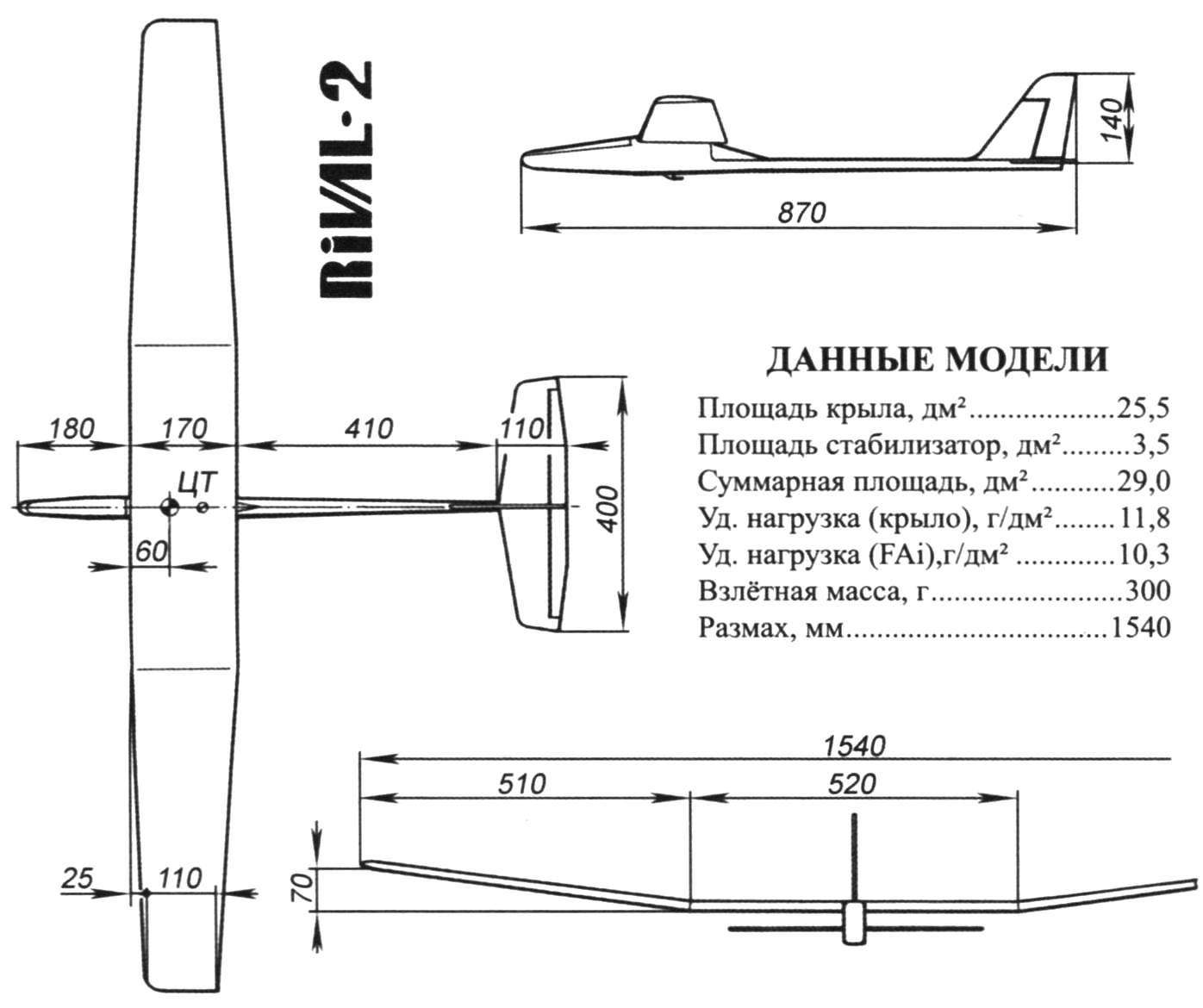
To date, the established “standard” designs in this class, fortunately, does not yet exist. However, now came to a common opinion that the wingspan of such gliders should be 1200 – 1600 mm, and their optimal weight is in the range of 300 – 400 g. moreover, we note that successfully used the gliders wing span 1000 mm, or even 2000 mm. Minimum weight is not the most important, because good results can be achieved with polukilogrammovy the glider.
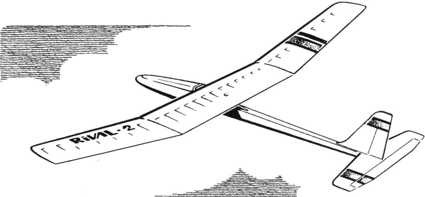
And yet, despite the variety of techniques already exist a kind of “standards” forget about when designing a new missile airframe is not worth it. One of them is the Rival glider-2, which constructed one of the largest and well-known specialists in the field of such model – engineer P. Lishak (Czech Republic). The story of the creation of such radioplayer has more than a dozen years. But since that time, none of the published in foreign magazines models surpassed Rival the sum of the parameters. And that’s why today we present this glider for travelers new to the Russian class.
We offer you a model glider designed for flying in small areas. The device is well behaved when “cannon” starts with ejection systems (10 m rubber and 40 m nylon thread), surely is towed on a normal rail length 100 – 150 m and provides a spectacular take-off with his hands. Exclusively flies and the streams flow over slopes even a small height. The model is well controlled and, despite the low specific wing loading, without any problems piloted even in a strong wind, with high “permeability”.
It should be noted here, that clearly shows the attitude of the designer to create their machines in the first place as a purely “entertainment”, and only then to the sports apparatus. It is typical for people who are passionate about creating the model and for which sports issues are secondary. Perhaps that is why P. Lishak successfully experimented with a good technique and in other classes of radioplayer, and lately it’s all about electrics. “Rivalo” successive generations of electric were able to show record results.
The first prototypes of gliders originated in 1988. These models were successfully used on football fields and stadiums. Good aerodynamics is preserved after installation on one of the gliders motor Mabuchi RS-380 pole and the power supply voltage of 9.6 V with a capacity of 0.5 Ah.
Operation of a prototype of unusual design has attracted the attention of other modellers. Know at least three similar machines, one of which was successfully used in class F3J (!), the second showed absolutely unique results starting with the hands, the third had a fiberglass fuselage with built-in electric rotor. And how is flying the new generation – Rival-2, you know at the end of the article.
It is interesting to note that gliders such schemes was not so sensitive to the increase in wing loading as you would expect. Although the achievement of the stated in the article weights the individual elements of the model and can serve as an indicator of class of operation, still it is not indispensable. However, a lighter model will be calm and terminou weather to behave better heavy.
DESIGN MODEL
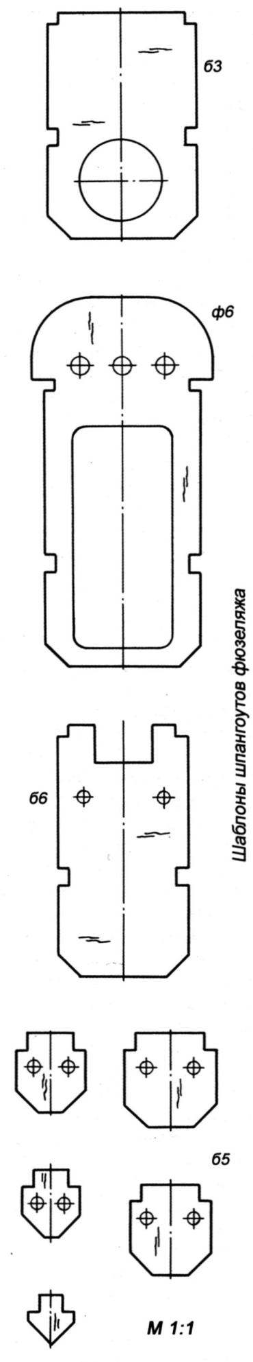
Thanks to simple and sophisticated design of the build is fast and without problems. It begins with the selection of balsa, which should be both easy and hard. Note that the jigsaw you will need in the manufacture of a single plywood bulkhead of the fuselage, but a pair of small connecting plates of the wing spar. Other parts balsa and cut benefitted only a scalpel or hobby knife (or razor blade hard). As the adhesive best suited cyanoacrylate “instant” adhesives, are known to us as “chakrini”. For sufficiently accurate adjustment of parts connecting with them will give strength only performed on epoxy resins.
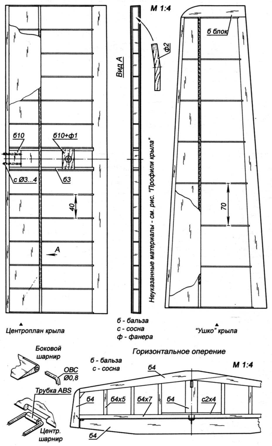
Wing. Rib ears cut out template, either individually, or in packs, but with the attachment between all pieces of the ribs of the plates remote from scraps of soft balsa with a thickness of 7 mm. Frames and center section of ears collected separately on a flat Board-stocks. End rib of the center section placed perpendicular to the slipway. The root rib tabs – at an angle corresponding to the “V” of the wing.
Small remark. Not very logical seems such a big difference in the step of ribs in the center section and ears. In General, you can see what initially caused this decision. But it seems to us that the ribs and the center section could be put equally rare. Suppose that mm balsa covering forehead perceives a large part of the bending loads acting on the wing together with the spar. Even if so, to reduce mass, increase rigidity and strength useful in centroplane frame to enter the diagonal spout-polonaruwa.
Still, having rich experience working with Mylar film, it may be advisable to Supplement the end rib of the wing and root rib tabs upper belt mount. This will allow you to securely glue the Dacron to the frame in the most difficult stitched. Otherwise you have to glue the detached film.
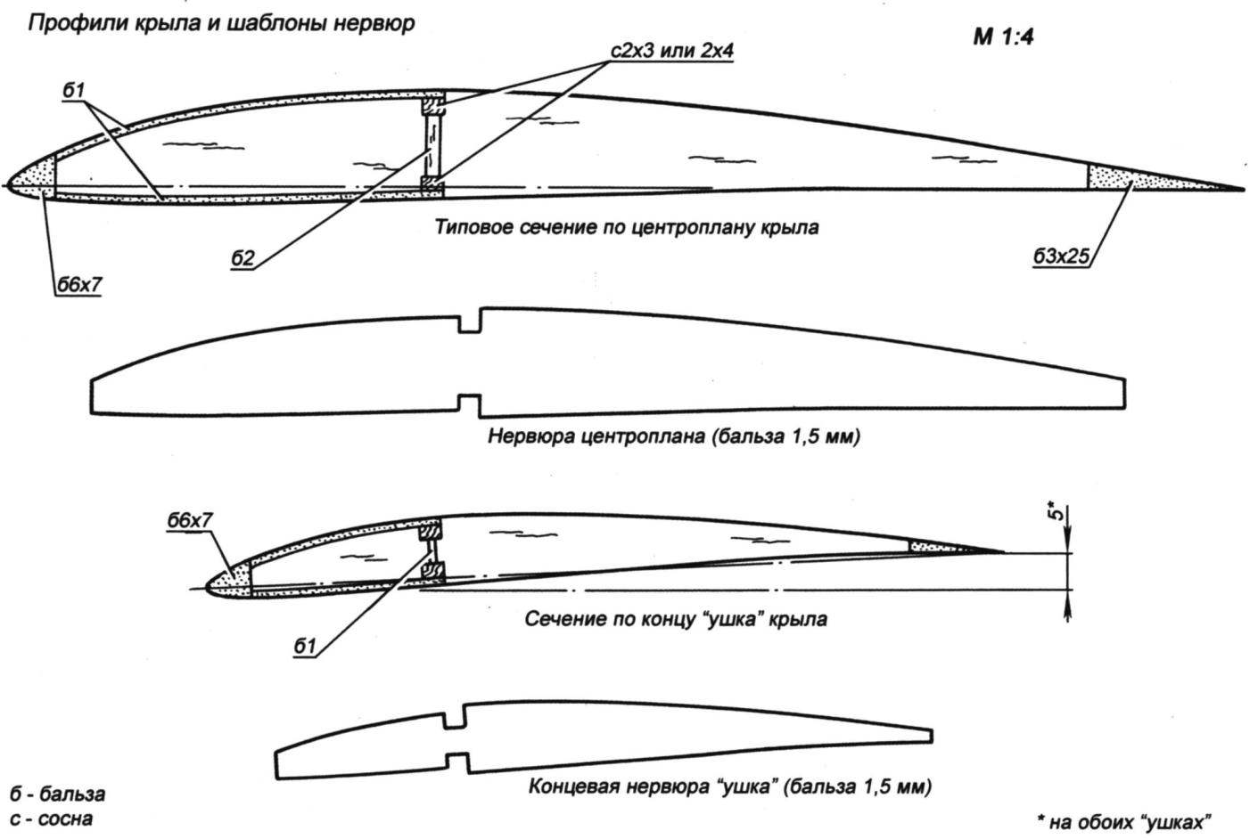
The wing profiles and templates for the ribs
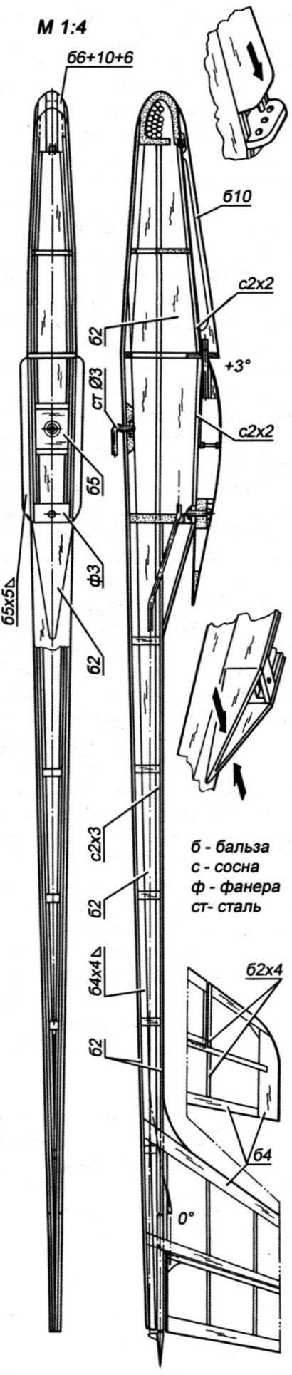
Fuselage:
b – balsa; C – pine; f – plywood; St-steel
The tough skin of the forehead, the wing is better to stick to the frame only after the calibration of its thickness and smoothing the surface of the veneer. First glued the lower part of the skin, then the balsa spar wall. Boss under the pin and screw fixation of the wing on the fuselage adjusted so that they are well fit as the bottom of the casing and to the Central double ribs of the center section. In the last turn mounted to the upper hard casing. Note that before this operation the rear edges of the ears need to invest a wedge-shaped slats. They should set a negative twist 5 – 7 mm at the end ribs of the ears. Circuit coffered lobikov the upper part of the skin will lead to a sharp increase in the torsional rigidity and, consequently, to the inability to specify or correct the twist in the future. The finished center section and the lugs are joined together using plywood panels serve as the walls of the spar on the transient phases of the wing.
The wing is fitted by a Mylar film or a high-quality paper type mcalenney. Modern obtiene film should be avoided as they are too heavy and do not provide extra rigidity of the wing due to its excessive elasticity. When working with paper and amoritami dry the wing need to secure it in improvised patterns.
The fuselage. Previously on the top bar of the tail boom mount the appropriate frames. To the side of the fuselage (note – they have a technological connector at the top of the spar, so the fuselage conventionally consists of the lower part, passing in the tail boom, and add-ons) are glued pine slats spars and balsa-tions of slats of triangular cross-section forming the bottom chord of the spars. Then through the webs of the beam is carried out a tubular sheath of wire rods for the rudders. The top panels of the tail boom attached to the bench, glued the prepared side. After the glue dries, you can adjust and setup the bow for the boss made in advance. This operation is also preferably carried out on the slipway, and the front part of the side panels must hang over its edge.
It is time to remove the fuselage from the pile and to engage in the installation top. This glued the front frames with the already mounted with the attachment of the wing. Now we need to build up the sides and framing them on top of the pine stringers. In the front compartment on the glue Board is the power switch, and underwing – flat boss with a tow hook. Then fit and glued in place the lower panel of the fuselage skin. Finally triangular shanks “pylon wing” trimmed and reduced to each other. On top of the resulting cone is sheathed with plate of light balsa.
Interesting and the technology of Assembly of the fuselage with conditional division of the height into two parts because of the emergence of the triangular fairing makes to argue with the author. The fact that between the shank of the profile of the wing and the fairing creates a wide wedge-shaped gap increasing in height toward the trailing edge of the wing. Aerodynamics, in General, very clean model that can’t be good for it.
We recommend you to try to reconstruct the fuselage, conditionally changing the upper and lower half of the technological places. Thus the fuselage part, which passes into the beam will move up directly under the wing – and the need for a fairing will disappear by itself. The resulting bottom “swelling” of the fuselage may be gradually reduced toward the trailing edge of the wing to the bottom panel of the tail boom.
Blank cover front compartments stuck on “spots” of glue to the place processed to the required shape and then removed from the fuselage. If desired, the cover can be hollow for lightness. In the rear end is glued a bamboo pin, and the nose is placed on the bottom plate of thin plywood, for which the cover is pressed against the lug with a wire spring.
To control the connectivity and correctness of the relative position of the wing mounted on the fuselage. During this inspection on Board the balsa fairings glued transitional and clarifies their lines. After undocking, the fuselage is processed completely, a little rounded all external sharp edges. On the outside it is covered long-fibre paper.
The tail Assembly. By design, the rudder is so simple that it is not self-explanatory. Only quibble about the figures of the suspension system of rudders. The proposed scheme with microamperage fully justified. It is noted that these nodes be embedded in the body of the rudder so that the gap between the rudder and fixed rudder was minimal. Then it will be provided not only increased the efficiency of the rudder, but also precise control. The cording tail – thin Mylar film or long-fibre paper. Control horns sawed out of thin wood and glued into the rudders. On the fuselage, the empennage is mounted after finishing the fuselage and tail (of course, all the layers of finish on the joints are completely removed).
There is another point which I would like to clarify. It is a necessity in the Horny compensator rudder. Or rather… his uselessness. The presence of “horns” not only complicates and weakens the overall construction of the vertical stabilizer. He, as one might expect, reduces the effectiveness of control on the course. The fact that a simple steering wheel can be rejected at an angle up to 30° without significant loss of its effectiveness. And on the rotatable plate (which is the entire top of the helm with a Horny compensator in the proposed drawings) the flow completely breaks down at angles that are equal to 10 – 14°! So keep in mind that the vertical tail can be safely reconstructed. Moreover, the compensators typically used only to reduce effort in steering linkage and steering wheel-cars, in this case it is not necessary. And so under these flight conditions and sizes of feathers even at maximum deflection angles efforts hardly reached 100 g. it Appears that the greatest effort in the management system will occur… due to the use of even such flexible rods, such as steel wire diameter 0,6 – 0,8 mm. the virtually straight-line linkage is only possible with the above proposed reconstruction of the fuselage. In this case, can not be avoided, at least three curves on each “Bodine”. And this is the inevitable growth in the value of friction that will be sensitive, with low capacity batteries. By the way, it would be interesting to measure the efforts in both variants.
Installation of the equipment. This operation is slightly complicated only a comparatively close with a volume of the fuselage. In the present embodiment, the wheel machines are not on the screws, and clamped between glued to the sides of the cubes of balsa. The fit and installation of machines on the sides with double sided tape. In an endless race for weight reduction you can without much fear to remove the receiver Board from its housing and push it in the compartment of the fuselage between the two blocks of polyurethane sponge. Similarly fit and the battery pack. The antenna is pulled through the slot available at the bottom of each of the frames of the tail boom.
Weight characteristics. Item (g): wing – 85, the fuselage tail – 85, the battery pack 270 touch 50, a receiver 24, both the wheel-cars – 56. Completely ready to fly, the model has a mass of 300 g.
Flights. Even the first starts are not bring any surprises if the model is constructed accurately and the centre of gravity is at a specified place, or slightly ahead of him. With a light cast against a weak headwind, the glider should be held about 50 m. Towing on the guard rails or start with a catapult doesn’t. It is useful to keep in mind that when the catapult launch glider vigorously pushed almost up. To preserve the stretch of the rubber in the initial phase of takeoff, the Elevator is strongly trending up. If you now approaching the top of the take-off to put the wheel in neutral, and then again to pick it up, it is easy due to the effect of dynastart to a win at heights up to 15 m.
Rival-2 is very volatile and has a wide range of speeds. After a short period of habituation to the management of this glider you can easily implement an exact fit in the hand. Note that circling at a height of about 1 – 2 meters or piloted loop to be performed immediately after manual start, do not belong to the figures, the caller concerns. And the high aerodynamic quality of the model not only puts the flight of a football field (again when running with the hands) in a number of unusual achievements. The strength of the device is sufficient in all modes of flight. It is interesting to know that the Rival-2 faithfully served his designer for over five years.
EDITORIAL:
In conclusion, in addition to our recommendations to create the proposed drawings, your Rival-2 and know all its flight characteristics, it is useful to remember one fact.
In one of the last issues of the magazine FMT (Flug – und Modell-technik) published descriptions of modern models of the same class and its test results. Throwing this glider is made with a wide use of composite materials.
The skin of the forehead, the wing is laminated from Kevlar, beam flange, the entire rear edge and the edging rib – CFRP, the fuselage is of Kevlar and coal, similarly performed and V-tail. Immediately reminded of the championship Svobodnaya gliders F1А in elite performance… at the same time and the whole history of class F1A. There is a race for results has led to unimaginable growth opportunities models paritala. And at the same time to their constant complexity and… to a sharp drop in the popularity of the class. He simply became extremely complicated and inaccessible to modelers, is not able all my life to devote to it, and only such gliders (in other words – it became unavailable for non-professionals).
Publication FMT alerted-surely a similar fate awaits throwing gliders? But, apparently not. Why made such a conclusion? First, the “happy” price of similar products. For entertainment this superplane seem to acquire only a “crazy” (by our, Yes, certainly, compared to international standards the model is not perfect – the skin of the forehead is noticeable puzyrit between the ribs, the photographs show the mistakes made while building the tail and so on). Then, this machine produces is not widely known, and, perhaps, by the author of the development, and in the form of single specimens of manual work. But the main thing is in all respects inferior to glider the same Rival-2, which makes the first even losing the competition.
Judge for yourself. The wingspan of the glider German modelers equal to 1480 mm, with an area of 23.4 dm2. Rival-2: 1540 mm and 25.5 dm2, respectively. Weight only the models themselves equal to 192 and 170 g (here and below, second value belong to the Rival-2), and this despite the use of the first model of “space” technologies and that it is less! Weight side parts of the control equipment – 152 and 130 In the result of a carbon-Kevlar machine has a total mass of 344 g. a Rival-2, as already mentioned, the 300, the Specific load on the wing equal to the first model, 14.7 g/dm2, and for the second, and 11.8 g/dm2. Hope there’s no need to explain?
V. ZAMOLODCHIKOV
Recommend to read
 BUILDING THE BOAT
Despite the fact that the industry produces many different small vessels (including yachts), the number of homemade, Amateur-built, grows from year to year. They boldly experiment with... SHEET CONDUCTOR
If you have to saw a certain number of wooden rods with a strictly perpendicular end faces, it is advisable to pre-make auxiliary guiding means conductor. It is necessary to take...
