The frame is cut from non-foiled fiberglass thickness 2-2,5 mm. “Ears” (cargo-balances) is made of brass or steel with a thickness of 0.8—1 mm. Pendant “ears” lutova, its structure is clear from the drawing. Longitudinal and transverse travel of the “ear” of about 1.5 mm, a vertical — about 2 mm on the outer edge and minimum at the inner edge of the rear support. Front sleeve has a diameter of 2 mm, and the rod is 1 mm.
Rear axle needs to ensure the constant engagement between the gears. This strut bearing on the gear side is done with a long bearing surface, with the front rivet extended forward from the motor shaft, which is mounted on frame with three screws with countersunk heads on the bottom. The plastic driven gear (electric shaver) rastaquouere and is joined to a disc wheel with an interference fit of 0.15—0.2 mm. wheel — turned, made of aluminum or caprolon. Tires: rear material imported beach Slippers, front — of polyurethane foam or polyethylene foam.
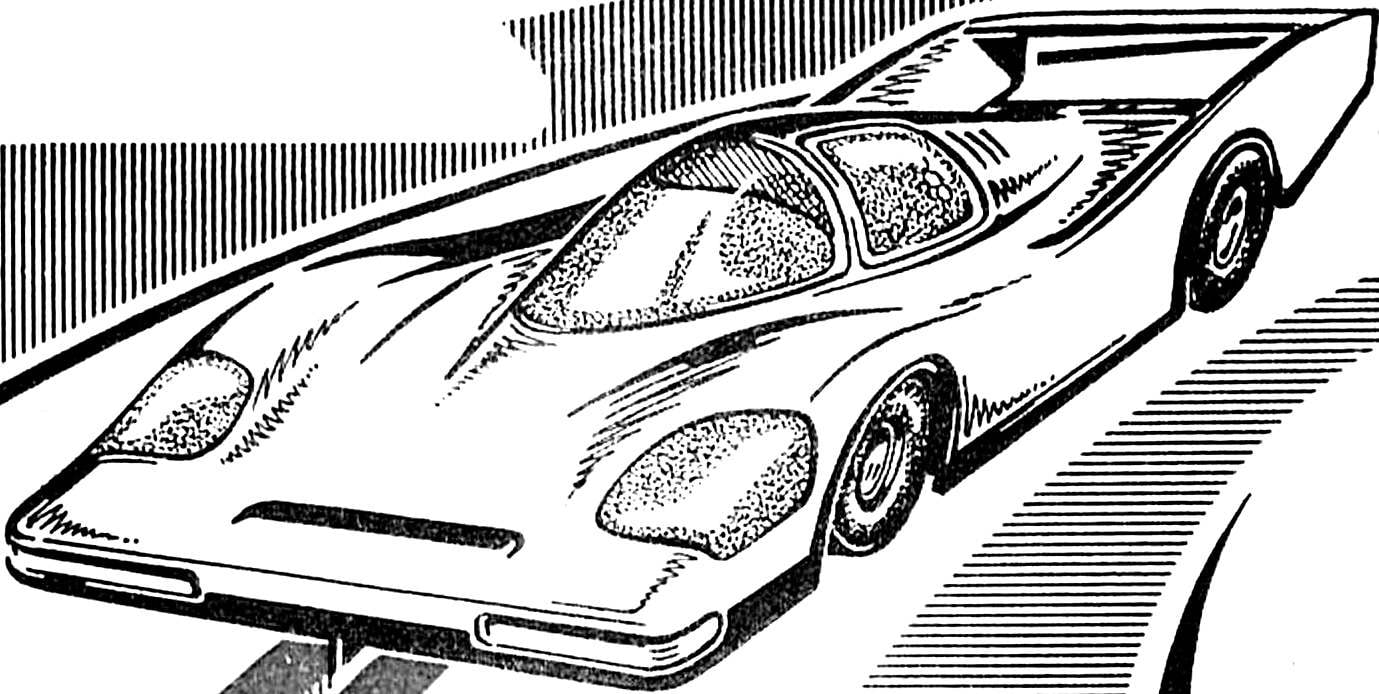
The body is made from a thermoplastic film of PVC, PVC, ABTS, or the like by vacuum forming (one of the variants of the technology have already been published in “M-K”). As a prototype you can use any car groups C1 and C2 after the release of 1981 — deviation from the scale is within tolerance.
Now the most difficult part of the model engine. Based on the motor D-1-2 (MPP-004). However, as a result of modernization of it is a little: housing (part), magnets (with completion) and iron anchors. Self-made back cover with brush Assembly, the socket of the front bearing, shaft, manifold, electrode and sleeve armature winding.
Engine DI-1-2 after the alteration. The cut lamellas of the collector is conventionally shown with the technological seam allowance for ease of sizing. Side view shows the engine with the removed mechanism the same brush.
Chassis model class TA-2.
Cover is machined from type alloy D16T, V95 or other similar hardness. Filing it (in size, taken with the drawing scale) after docking with the case.
The housing should be cut to length and drilled the hole for the bearing in the front wall. Both operations perform better on a lathe. On both sides of the axis of the body symmetrically cut to size 17 mm. Then attach the cover and fix it with screws (four M1. 6 or M2). The most difficult operation of compression of the hull at the front wall of 1.5 mm without deformation of the shape of the walls, which is adjacent to the magnets. But to carry out this work is necessary because the standard gap between the armature and magnets is more than 1 mm. Any accessories required, if the crimp to hold in a vise, fixing vigibase front wall with pliers. Then solder the legs of the engine mount on the frame and nuts to them. Mounting the motor on the three screws. Wide leg — with two nuts from the rear axle; narrow — a single nut on the opposite. Material paws — brass thickness of 0.5 mm or roofing iron. Cover is cut according to the height and there are Windows to the brush site. Machined from brass or steel socket front bearing sealed on the housing.
Magnets need soshlifovat edges, protruding outside the case, and not overheating the magnet itself and not cooling it in water. Grooves shown in the drawing, propisyvayutsya diamond needle files or fine vulcanicum drive. The magnets are mounted using epoxy and brackets from soft wire.
The shaft will have to be replaced by hardened tool steel Ø 2 mm, or 3 mm of steel “silverfish” (as it is abraded, it is visible in the figures). Transitions from one diameter to another should not have sharp inside corners, otherwise there is a high probability of breakage of the shaft.
Regular plate anchors if necessary rassverlivajut. The package of plates and insulating plates made of glass fiber with a thickness of 1 mm collected on the epoxy with a press fit to complete the curing of the binder. The slots of the armature are glued strips of paper for insulation. Set between the armature and the front bearing, and also between a set and a header are printed sleeve of triangular cross-section. Their length is adjusted so that the anchor had longitudinal backlash between the bearings is approximately 0.2 mm. Faces of the bushings can be filed in order to be able to lay exactly the winding.
Insulating bushing manifold with two flanges machined from the PCB, and the rod of lamellae of red copper. After processing the last is marked for cutting at the knuckles of the cartridge of the machine. When cutting of the workpiece need to leave the “tail” with a length of 5-7 mm, in which it is clamped when cutting. Slats, and a “horn” for crimping are performed with a jigsaw with a blade for metal, then separated the “tail”. Crimp brass ring — the maximum width at a wall thickness of 0.2—0.3 mm. Clearance between the ring and the lamellae are about 0.2 mm. When building the slats are mounted on the sleeve, lubricated with epoxy resin, wrapped two to four layers of resin-impregnated newsprint and then skewer tight o-ring. While a binder is not hardened, using a thin awl to expose the gaps between the slats. Before Assembly of the manifold all parts are degreased with alcohol.
Diagram of the winding shown in the drawings. It is executed by a wire PEV-2, PETV, PETV-2 with a diameter of 0.31—0.35 mm, 60-70 turns. It is necessary to achieve complete uniformity of the windings, so the windings are placed very tightly. Useful to record the number of turns in each layer, especially when the first attempt of manufacture of the engine. If something does not like or will not very successfully, the coil be sure to remove and do again. Ready to “coil” is impregnated with an epoxy resin (impregnated with it, not poured!) and, before hardening, the anchor is placed in a drying Cabinet or in close proximity to the incandescent lamp, collector down. Ready the anchor is put in a lathe and face piercing holes in the manifold.
Diagram of the armature winding.
Procurement of commutator bars.
Brushes are made from selected empirically material. Their cross-section 3X3 mm, where as blanks is better to use a brush. If there are none, to the end brushes of the conductor sufficiently thick and soft “cord” to hold the spring. The brush holders are curved with a soft brass 0.3 mm thick in its simplest frame. Under them I put a strip of fiberglass 0.5 mm. mounting Screws are insulated from the holders textolite washers and PTFE tubes. Spring — wire Ø 0,5 mm, are wound on a rod of Ø 3.2 mm, have 5 coils and in the Assembly dressed in cups Ø 3.5 mm. In the place fit to the brush spring set Teflon tube. The contact force depends on the material of the brushes and the collector, the speed of the motor, current value, quality of balancing, therefore, is chosen empirically. Engines assembled according to the proposed technology, it is possible to “spin” under load, up to 35,000 rpm.
The same method can be used to alter and other motors. For example, D-1-3, or imported if they are close in design.
It should be noted that to put on a textolite frame powerful and dynamic motors with samarium-cobalt magnets is not: to find a compromise between the characteristics of stiffness, mass and vibrational properties fail. For the rest, never forget that when creating a model there are no small things!
A. NESTERENKO, Leningrad
Recommend to read PAINT WITHOUT SECRETS Assortment of paints (coatings) are currently quite wide, and therefore, in such a variety without the advice quite difficult to understand. Get expert advice from the seller not always... THE WIRE — THE To harden a steel part in a domestic environment, it must first be heated, as, for example, on a gas burner. However, the question arises: what is its holding? Pliers or forceps are not... Scroll back to top
 In the “M-K” (No. 11, 1990) was described by the model of the strongest tracks. However, the production of such equipment is not available to everyone and is quite expensive. And what do the athletes do not have much experience, and beginners in the club? For them it is proposed to develop a model of THE class-2 modern design, but runs out of available materials and without using complicated technologies.