Let’s start with econometer. Such devices are available in small industrial series. You buy them hard, and not very convenient to use a dial indicator. The scale of the instrument is divided into three zones: a large dilution when the engine is running at high revolutions,the choke is covered, for example when braking the motor: the minimum, typical for a fully open throttle; and zone mean values of vacuum at which the engine operating in its most economical mode. The indicator in this case more rational. And to make it so.
Fig. 2. Electrical wiring diagram system
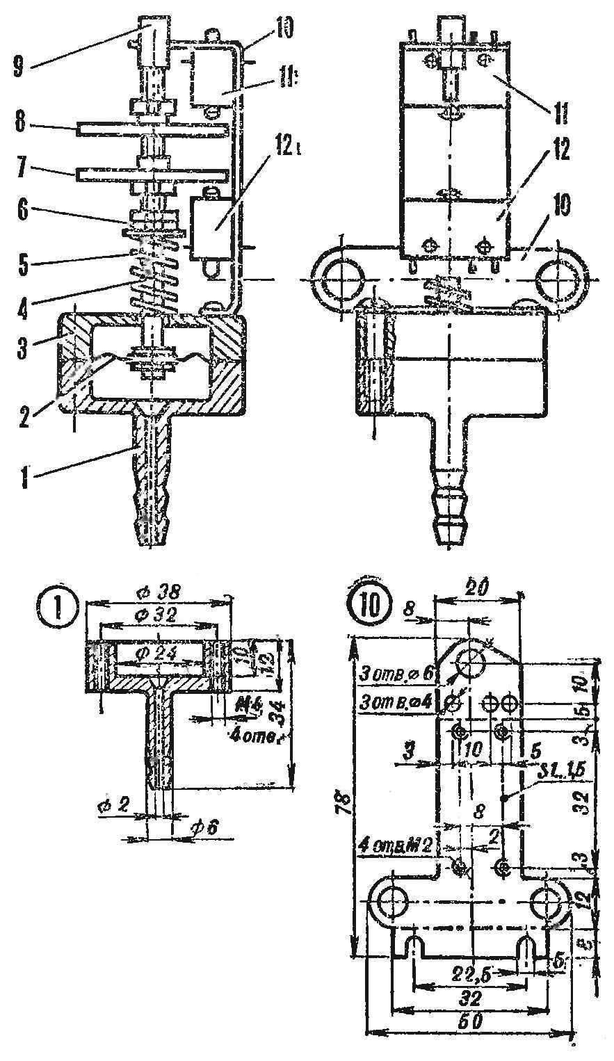
On the dashboard in the driver’s field of vision are mounted three indicator lamps with colored glass: red, green, and blue. The illumination of the respective mode of operation of the motor “eye” by means of switches. They are controlled by a simple diaphragm sensor vacuum hose connected from the intake manifold. (On cars with a vacuum booster of brake — through tee with hose amp.)
The vacuum sensor consists of a housing 1, membrane 2 and the cover 3, forming a membrane box. The diaphragm rod 4 is a pin with a length of 70 mm with external thread M4 for the entire length. It is equipped with two pressure disks 7 and 8 and together with the membrane pojad cover the spring through the adjusting nut 6. The thread end is closed by a tube 9 of Cambria and skipped in the guide hole of the bracket 10, which is fixed to two of the switch 11, and 12 MP type 3-1.
R and S. 3. Dutchin of dilution on the basis of the relay ART-2 :
1 — body, 2 — bellow, 3 — rod, 4 — bar-lever, 5 — Foundation. 6 — pin groups (solenoid), 7 — lid (plexiglass), 6 — screws M2, 9 rubber gasket, 10 — bracket, 11 — an insulating core.
At a small negative pressure under the membrane of the rod under the action of the spring occupies the upper position by pressing the disk 8 on the button of the switch 11. If you increase the vacuum diaphragm, compressing the spring slightly down the stem, the disc 8 moves away from the switch. Further increase of RA regenia makes the rod move to the position at which the disk 7 press the bottom switch.
The body and cap are machined on a lathe endurecimiento or brass billet. Aperture is cut out of varnished cloth or membrane automotive fuel pump. Spring (6-7 turns with an outer d of 10-12 mm) of the circumferential steel wire d 1 mm. its Elasticity should be such that when the vacuum under the diaphragm is 0.7—0.8 kg/cm2 deformation was 4-6 mm. Billet bracket cut from steel plate and 1-1. 5 mm thick, drilled and bent as shown in the figure.
Fig. 4. A diagram of a system with a sensor on the ART-2
With signal lights terminals of the switches are connected according to the scheme shown in figure 2. Thus, at the maximum vacuum in the intake pipe (forced idle, the movement is covered by a throttle or air valve) will burn a blue light; when driving with full load (throttle fully open) will illuminate red, the most economical mode — only green.
Before installing the vehicle sensor adjust to the switch 11 is triggered at a pressure of 0.1—0.2 kg/cm2 , and the switch 12 is at 0,6—0,7 kg/cm2. Properly adjusted, the device should work. The uniform motion along the horizontal stretch of highway with 1-2 passengers at a speed of 80-85 km/h light green light. At the slightest acceleration it goes off and the red turns on. If, without turning off the transmission, reset the gas will light up blue light, and decreasing speed to 20-30 km/h — green. When working on the engine idle speed should be steady green signal when a sudden pressing the accelerator pedal — red, and with a sharp reset — blue. Focusing on these indicators, it is easy to develop the most economical driving style, when ekonometri the green light.
There is this small sensor and lack. So how do the switches by pressing and releasing the buttons require some effort, is not the same for forward and reverse, sometimes there is a small spread of readings (approximately 0.08 kg/cm2 or 10 km/h for speed).
This drawback does not have the second variant of the sensor shown in figure 3. Its design uses parts from temperature switches ART 2 of household compression refrigerator and a contact group from the electrical relay.
The sensor consists of a casing 1 with bellows 2, ART-2, traction 3, lever 4, the base 5 with the contact group 6 and cover 7. Two contact groups are attached to the base with screws M2 using the rubber strip 9. Soldered to the lever bracket 10, operating their ends on the middle contacts through the insulating rods 11.
In the manufacture of such a sensor is also quite simple. The base is cut from thick steel plate and 1-1. 5 mm; bracket-lever — brass with a thickness of 0.2—0.3 mm, and pull out strips of brass or copper with a thickness of 0.5—1.0 mm. It is soldered in the center of the bellows and acts on them is 2 mm.
When mounting contact group, mounted on the base so that one of them is switched when you move the bracket down and the second upstroke. The lid 7 can be used from thermostats ART-2. Electric connection diagram shown in figure 4. When assembling the bracket podymaetsja: the right contact group, wrung out the clip up, closed on the upper contacts, and the left in a free state — also closes the upper contacts. With increasing dilution than 0.1—0.2 kg/cm2 the lower part of the bracket away from the right group. At a pressure of 0.6—0.7 kg/cm2 switches the left-hand group of contacts.
Fig. 5. Revision shut-off solenoid valve for ustanoveni the system idle econimizer :
A — machining the valve body; B — grinding of the needle — adapter.
The moment when rough is installed by tucking staples, and sure — tightening mounting screws 8 — due to the deformation of the rubber seal 9.
Both designs of vacuum sensors provide the ability to connect electric shut-off valve of system of idling, that is, the equipment engine economizer forced idling (idle cut off valve). This valve is equipped with engines of VAZ 2103, but it is used only for forced ceiling system idle ignition off. If the engine is to complement the proposed devices, the car is equipped with and system of idle econimizer.
Kit shut-off valve with solenoid control is passed to the spare parts, and after a little rework can be installed on the carburetor DAAZ 2101-11-1107010-11. The housing is shortened by 12 mm threaded M12X1,25 (Fig. 5), the shut-off needle zashlifovyvayutsya fine sandpaper to a diameter of 1.4 mm and made an adapter.
During Assembly, the needle is inserted into the housing and then breaks through the adapter. If the connection is not sufficiently airtight, install paronitovye the gasket thickness of 0.5 mm. The assembled nozzle is installed in place of the plug covering the idle jet. The needle should shut his face hole, and when fed to the winding of the valve solenoid voltage to move away from him and free flowing fuel.
Developed a system of “Light econometr — idle cut off valve” is operated by car “Moskvich-2140” since 1981 and has established itself well. Its application has allowed to reduce fuel consumption 1.5—2 l/100 km. Eliminated the tendency of the engine to the ignition of the mixture after the ignition is turned off. Toggle forced off of idle economizer valve allows to neutralize the system at a time adjusting the carb and use it as anti-vehicle.
B. Kobtsev, Orel
Recommend to read PUTTING THE IGNITION Engines MMVZ-3 115 often used on maps and — with appropriate upgrades-cooling system — tillers and microfracture. Among the works on their service, there is also such as installation of... Gas soldering iron In the practice of auto and motorcycle enthusiasts, one often has to deal with the need for soldering or welding. Several years ago I quite accidentally saw a gasoline soldering iron made... 
 Growing every year in our country, the number of motorists. For many of them the car is not only a means of transport, recreation, but also technical creativity. It would seem, than still it is possible to add, improve released in a modern plant the design of a brand new car! But for the curious enthusiast with skillful hands here even boundless field of activity. To them and turned a new section of our magazine “Car “M-K”.