 The fuselage of modern rezinomotornaya model aircraft usually consists of two parts: the power (it houses the rubber motor, is attached to the lug screw, wing) and the tail boom carrying the tail surfaces. The power part usually is a thin-walled pipe of aluminium alloy, plywood or fiberglass. Tail boom made in the form of a light truss or stacked monocoque construction with hard balsa covering.
The proposed beam belongs to the second type. Has a high adaptability, efficient use of material, good strength and weight characteristics.
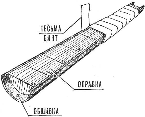
Running it from two symmetrical half-shells glued together in the plane of symmetry (horizontal or vertical). It should start with the manufacture of lime mandrel for flexible sheets. Knowing the outer diameter of the power pipe and the length of the tail boom, made it in the form of the cone, cut along the longitudinal axis (Fig. a). The conical surface has a negative allowance., the selected thickness of the balsa covering (usually 1,5—2 mm). In cross section the required allowance 2-3 mm, to remove subsequently submitted covering edge and be able to correct errors made during manufacture. On the flat part of mandrel you need to mark the axis of the future frames, the mandrel is carefully treated and coated with several layers of Amalita. Then cut out the trim (2 PCs.) as shown b. The resulting billet should be soaked in water until complete impregnation (15-20 min.). After that she strapped to the mandrel as shown in, tape or medical bandage. Primado lead tightly, but not tightly, so as not to cause deformation.

The sequence of manufacture of the tail boom of the fuselage of the model airplane rezinomotornaya:
a mandrel with marking of frames, b — billet plating, in— Primate plating to the mandrel g — set polosamota, d — tail boom Assembly.
After drying, the shells received a pencil, mark the installation location of the frames, using the markings on the mandrel, and put on glue polosamote. It is better to make balsa plywood with a thickness of 2 mm. Pre-glued in the appropriate places straws that serve as the channels for the wiring linkage from the timer mechanism rebalancing and the deviation of the stabilizer. Fixed in a vertical plane in the zone of maximum building heights, these straws simultaneously perform the functions of the power beam elements. Once both shells are all polosamota and do the necessary internal work, they are steel strips can be sandpaper glued to a long Board to the correct size (cross-sect. A—a to the picture) and glue the halves of the tail boom, split pins (Fig. d).
Note. If you use enamel, it is best just outside to soak the joints with acetone or WFD, which rezeigat layer of glue that will ensure a secure fit.
After drying, smooth out the beam and set it the necessary external elements (the attachment of a stabilizer mechanism of rebalancing, Kiel, etc.).
Similarly, you can make the tail boom models of gliders and “timerock” taking into account the specific features of their fuselages.
O. LAGUTIN


