Now the requirements for in-flight properties:
— minimum steady flight speed, providing the time for making the correct decisions necessary in the absence of automatism from an inexperienced “pilot”. It would be good to vary flight speed in the widest limits, then learning later it will be possible to keep it up
prior to the transition to modern sports equipment;
— high resistance and good handling. The sensitivity of the controls – ideally, can and should be regulated. In addition to a wide range of speeds, it is desirable to have the possibility of significant changes to the load-bearing properties that turn either model into a good glider-soaring leader or flight microplane;
— need and high academic power-saving model when entering unexpected for the novice pilot’s position near land;
— should be good and performance: without any problems like “universal” obliged to fly with it.
Might sound that demands too much, they are too contradictory. Unthinkable to do such a study. . But still let’s try!
In accordance with the first condition of flight properties select the type of the model glider. More precisely, the glider, and with a powerful engine, having the control of “gas”. This, in turn, will provide high power models if its mass is not too large, and simple take-off.
Now, about the mass of the machine. The fact that it is not only closely linked to the minimum satisfactory strength, but with the choice of the main dimensions of the training. Taking the specific load on bearing surface is 25 g/dm2 corresponding to the load is very good paritala, and choosing an engine, we can find the total area of the planes.
The engine needs to be selected based on the maximum ease of starting in all types of winter conditions and the ease of operation of the entire plant. Most suitable motor KMD-2,5 . With the glider, equipped with this engine, it is possible to train all year round, it is sufficient for a small, even aerobatic models, it has a significant resource and keeps stable mode in a wide speed range.
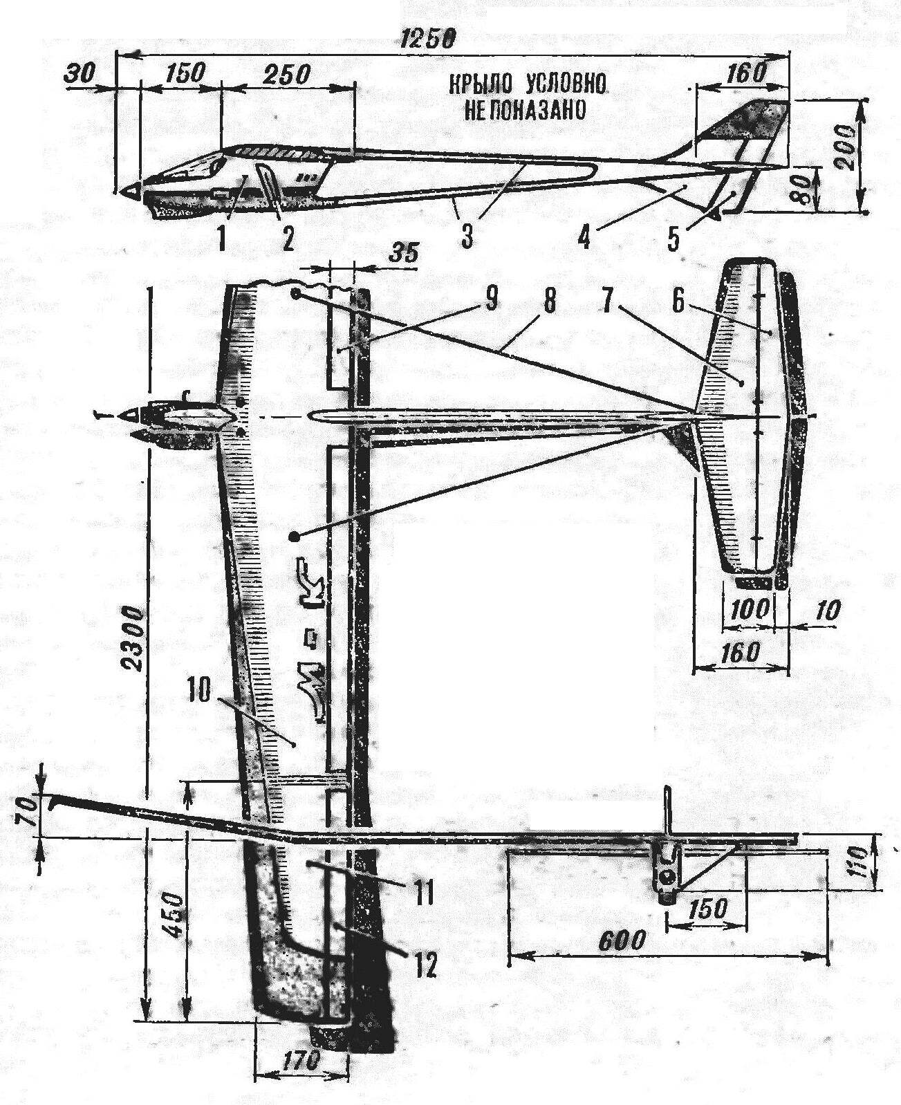
The design of the stabilizer :
1 — ending 2 — ending steering, 3 rear edge steering, 4 — filler 5 — flange wheel, 6 — , the rear edge of the stabilizer Assembly, 7 — boss 8 — solitaire, 9 — Central rib, 10 — rib,11 — polonaruwa, 12 — spar. 13 — the leading edge.
The mass of the plant in combination with fuel system may not be above 200 g. four channel proportional side of the domestic equipment radio “Suprana-83” has a mass of about 650 g, which gives the total weight of the equipment along With rods, fixing points and mounting panels 900-950 g
How many grams to take on the design of the airframe?
Let’s see what happens if you take the preliminary calculation of the seemingly fantastic figure, So weigh 500 g. championship free-flying priteli much smaller, flying with only “pedestrian” speeds. We have the same total area of the bearing surfaces, obtained after determining the total mass of the model turns out to be one and a half times more — about 55 dm2.
THE CHOICE OF PARAMETERS OF ELEMENTS
Will try to “stack” design in a very unusual frame mass. Suddenly let out! Let’s start with the wing. It weight makes the most significant part of the total.
Based on the fact that we are not worth the task of creating a record apparatus, and the good soaring conditions we provide low specific loading on bearing surfaces, it is possible not to chase high value of elongation. Its reasonable size will not only benefit the reduction of the weight of the wing and consequently will retain the supercritical Reynolds number for the secondary chords of consoles. You can easily pick up a simple execution profile that is fully compliant with us according to our qualities, even at minimum speeds. As for the strength and stiffness of the wing, determine its weight, then these quantities are nonlinear dependent on the elongation at planes the same profile. Reducing it twice, we with proper design can four times to reduce the weight of the wing!
And what about narrowing? Tempting, of course, to draw straight planes — they seem much easier to manufacture because of the identical shapes of all the ribs. But the tapered wing is not much harder straight. But increasing the strength of the root parts of the wide and reducing them the stresses of bending make it possible to further reduce the weight of bearing areas by 15-20% compared to direct.
Very technologically advanced, well-proven in thousands of models, undemanding to keeping in shape and quite “thick” is a classic “С1агк-In.” Its relative thickness is about 12%. As shown by comparative polars of a Plurality of profiles, at small Reynolds numbers “С1агк-” practically in no way inferior to fashion “applerock”, at higher speeds the win for the use of the latter is not significant enough to prevail over the technological properties of the classical implementation. And, as a rule, the advantage in aerodynamics affects the profiles series “E” only on part of the polars. Before us is the task of design is not fiber to the soaring leader and microplane-wagon
The solution to the aerodynamic wing will complete the introduction of mechanization across the trailing edge, providing the possibility of turning the soaring leader in flight (!) apparatus and task the angle of transverse “V” to increase the sustainability of the model. To the design of planes back when talking about building a training model.
The meaning* of the aerodynamics of the fuselage is an element, only connecting the wing with the stabilizer, unless, of course, has relatively large dimensions, which affect the stability and controllability of the model as a whole. Assuming that the fuselage of our system a significant effect on these characteristics will not have due to the small cross-section, we will look for only its constructive solution. The same applies to the tail feathers. Here only it is necessary to mention wishes to the loads transmitted from the stabilizer and fin on the aft fuselage. If you manage to get rid of torsional efforts, it will be possible to reduce the weight of this part. To do this, draw up plans, the keel of the two vertical surfaces of the square symmetrically over the stabilizer installed on the axis of the beam of the fuselage and underneath. The area of the stabilizer, providing quite sufficient for our wing efficiency factor horizontal tail, equal to 0.7, while the shoulder stabilizer about 4ВСах will be in the range of 7-8 DM 2.
First of all, about how to carry out the calculation of the elements of the glider on the strength. Of course, to bring it fully on the pages of the magazine is simply unthinkable because of the large volume. It is only necessary to mention the conditions adopted in the calculations. Is: the maximum flight speed of 120 km/h (!) and the minimum value of the radius changes the trajectory corresponding to the overload in the 8£, equal to 15 m! Conditions are extremely hard, such a characteristic is not for a glider, and for a good aerobatic microplane. But we are designing universal learning model, capable of flying and “acrobat”, and like a soaring leader.
We begin the story with the most important element of the wing. A considerable elongation of providing high quality value and a small rate of descent of the model with the soaring leader, even with a large contraction of consoles has given rise to enormous bending moments in the root cross-sections of ia elevated speeds. Under these conditions a good combination of Flexural strength and torsional stiffness could give a solution with a rigid bearing shell. But the bulk of these consoles would have been excessive, and we would not have been able to stay within the allotted boundaries of weight.
The decision gives the experience of designing light expense of building a traditional model aircraft. The rigid framework of the rules “taught” athletes to create a very lightweight wings sufficient strength and stiffness. Set consoles, similar to what is used on gliders and rezinomotornaya applies we. Dvukhpolosnykh spar with the wall will allow the wing to withstand the maximum loads under the most drastic evolutions, the torsional stiffness will give a series of diagonal ribs or struts in the root parts of the consoles. Section shelves of the spar variables corresponding to local bending moments in various sections of the supporting planes.
An important question arising upon the drawing of any new model, — on the necessity of introducing a Central contact of the wing. Typically, the solution connector is used with a significant size of the device, it facilitates transport and manufacturing wings. However, the loss in weight associated with the separation of bearing areas for the most loaded area is very high, not to mention the nodes of the joint and the connecting pins or plates-bagineti. Split down the center of the wing more difficult to assemble and manufacture, not easy to ensure perfect symmetry of the installation of the consoles relative to the fuselage. The node interface reduces the reliability of the model as a whole — a lot of accidents training apparatuses are caused by destruction of the connecting elements of the wing and fuselage, the decoupling is not accurately made of the node, or its deformation, leading to the displacement of the planes.
Thus, the educational wing will be solid. But how to transport “circuits” with a length of about 2.5 m? Connector need. We will transfer it to the area loaded several times weaker than the root sections. Will the detachable “ears”, in this embodiment, the maximum size of the dismantled plane will not exceed polurama. Installing the nodes in a lightly loaded area will reduce to the limit of loss in weight, and the total building solution will provide the option to further increase the versatility of training. Need “pure” soaring leader? Please! Enough to increase the angle of transverse “V” on the detachable elements and to lower the flaps. Speed the glider will give a locking of the flaps in the neutral position, a small rise will transform the former soaring leader in a good “pilotage” — properties of PLANO-convex profile .a raised flap close to the properties of symmetric. But the dismantling of the “ears” will make the model very close in flight characteristics to the microplane. Shortening the wing will reduce the load on the Central part of the spar, therefore, will not be afraid to display the unit on the highest speeds and sharp turns. In this embodiment, the reversible previously only ia the ground, the flaps must be transferred to control in flight as the ailerons with a small deflection angles. The possibility of correction of the average angle of their installation (as flaps) is maintained only for the ground conditions.
Will continue to work on the construction of the frame of the wing. The case for the trailing edge. The requirements of minimum weight with sufficient strength meets T-shaped “beam” that is collected from the two rails. Such use of us, it also makes it easy to place the hinge the flaps and ailerons.
To improve the aerodynamics of the model must be obtained in the manufacture of planes the profile as close as possible to theoretical. When soft the skin this can be done only by placing a large number of ribs with the mandatory installation of nasal polonorum. As a result, the number of these parts, especially on the wings of a glider type, and will determine a significant effect on the total mass of consoles. Hence, the weight loss of each of them literally fractions of a gram will help within the given takeoff weight of the apparatus.
As shown, confirming the theoretical calculations, the most favorable design of the rib with a “working lining”. The Central part, is virtually not loaded, performs the function of reinforcement strips siding from buckling under compression and, therefore, cut from light grades of foam (like packing melkosortnogo). And Reiki edging will take ia all the loading from the sail tension, and aerodynamic. Such ribs are well joined with the T-shaped trailing edge, in the area of spout them useful to strengthen the paste over both sides with paper.
Wing design :
1 Central panel, 2 — beam, 3 — edging of the flap, 4 — filler flap, 5 — a wall the rear edge 6 of the rear edge, 7 — rib, 8 — rib oblique,9 — spar, 10 — the tip of the flap, 11 — rib joint. 12 — the guide pin. 13 — ending, 14 — toe, 15 — cover, 16 — wall of the front edge 17 is the leading edge.
It should be noted, adaptability and cross charm set. You will not have to experience the difficulties associated generally with the manufacture of the ribs for a trapezoidal wing — for all consoles with any narrowing of the technology alone. First of all, the templates are cut and the root end section of the wing lowering the contour corresponding to the thickness of the “working shell”. With some heated by electric current of a wire from a foam block cut the workpiece. By “scope” it is equal to the total thickness of all ribs and olunurlar for one console plus losses for the next sawing into its individual parts. Using the remaining after cutting the foam pieces back profile, the clamps, sheathed billet lime or birch veneer in epoxy resin (the layers of wood — just across the wingspan!). If you want to increase the thickness of the “skin”, use several layers of veneer sheets, thick plate may not follow the contours of the profile on the most curved parts of the nose rib.
After complete curing of the resin workpiece is sawn into individual parts thin circular saw or converted industrial wirelesscom. Rib through one shortened, forming a nasal polonaruwa, followed pasting of areas of intersection with the front edge of the paper.
Wing Assembly is carried out by conventional methods. The only requirement is to provide maximum symmetry of the left and right consoles. The stabilizer design is similar to the planes of the wing, some of its elements only in reduced cross-sections.
The drive system of the ailerons and flaps are not shown on drawings — it all depends on the type of the applied equipment and servos. In any case, we should strive to place cars in the volume of the center section. This will help to get rid of unnecessary nodes in the intersection of actuator and the difficulties associated with preregulatory management on accidental discharges of the wing. And the fuselage will be possible to design smaller and lighter. Ideally, in the center section houses all the servos and receiver in the fuselage is only the power supply and the drive control gas engine. Thus further reduced the weight of the fuselage I decreases impact vibrations from operation of the plant ia the reliability of onboard equipment.
Plating of bearing surfaces — Mylar film of medium thickness. On top of it privacyrelated long staple (micuenta) paper. The result is a durable, puncture-resistant and impact plating of sufficient stiffness and roughness. Steering elements upholstered in thin Kraft paper on the PVA glue and finished the two-component parquet varnish.
As you can see, the wing and stabilizer (keel similar control elements) can be made according to the strictest standards of aviaconstructora, light, rigid and strong enough. Will try to do the same and the fuselage, still not forgetting the manufacturability training. It still was possible to do without the use of complex tooling, balsa needed except for “raising” of the spar to the level of the ribs.
The nose of the fuselage carries the engine and some elements of the radio apparatus and serves for fixing relative to the wing. Moreover, it is necessary to consider: the shorter the part, the less load will occur at the points of fastening to the wing and the harder it will be. Therefore Prorsum fuselage with minimal removal forward, assuming a small mass tail of the model. The midsection it is compressed to the limit, a plywood Board, sealed with a light longitudinal frames and set almost all s close round the engine, tank and side part of the apparatus.
It remains to decide which will be the tail part of the fuselage. There are many options, the best is… bestuality! Its function takes on a fork-lift beam. It combines such advantages as lightness, extraordinary ease of fabrication and remotepoint. Each shoulder beam is a square tube made up of four pine slats of variable section. In the transverse direction, the tail portion is fixed relative to the wing by a pair of braces from wire d 0.5 mm, the nodes of intersection of the beam with the fuselage and wing is split with the impact model.
Control linkage to the rudder of the tail rope, it is easy to hide inside the hollow of the shoulders of the beam. But at first, when the probability of accidents is sufficiently large, it is better to leave the cables outside. This will facilitate the readjustment of the system after repairs. Stop talking about management, we need to warn modelers from trying the drive flap. Their large area causes, even at low speeds the required control effort, far exceeding the capacity of steering cars of domestic production. Chassis model was not provided.
Recommend to read BMW Isetta Post-war industrial crisis has forced automakers in many countries to pay attention to cheap minicar — just like she had at the time a steady demand. Was no exception to this process and... SAVES REFRIGERATOR Anyone who used spokoinym glue, you know that, after mixing with curing agent (with gloves and under the vents: glue is toxic!) after a short time, it thickens and hardens; often, the... 
 We are all accustomed to the fact that it is a machine fit only to acquire initial skills of piloting. In most cases, training is built almost without any requirements for in-flight properties. The main thing — to provide the maximum ease of manufacture. Eventually, when the athlete will be accepted for the design of the following models with which it will compete, will be subject to calculations and aerodynamics, and strength of materials, and materials science. But at first — what to suffer, whether… And see the light polulotosa “snags”.