And, despite the interrelation of these requirements, the decisive factor in the choice of the scheme for us was the reliability of the model as a whole. After all, how many times even experienced athletes failed great vehicles with glow motors, with intricate clockwork, and there were modelers with a simple but reliable equipment! What can we say about the boys, just starting to get into a nervous situation scoring starts…
R and S. 2. Wing (left wing shown, right— wing console) :
1 — front edge pine (3X4), 2 — end rib (lip thickness of 3 mm), 3 — slip rib (1 mm plywood), 4 — pin xation of the brackets (bamboo d 2.5 mm), 5 — trailing edge (pine 1,2X12, complemented by rail 1X2), 6 — straight rib (1 mm plywood), 7 — oblique Polonnaruwa (plywood 1 mm), 8 — a covering (Mylar film), 9 — additional plating (micuenta paper on Amalia), 10 — shelf side member (pine 2,5X5), 11 — stringers (pine 1,2X3),12 — filling in the Central section (foam PVC), 13 — the spar web (the plywood is 1 mm, can be replaced by the sealing of the gap between the shelves with foam PVC), 14 — pin attachment on the center console (wire OVS d 2.5 mm), 15 — root rib (lip thickness of 3 mm) 16 — ending (plywood 1.5 mm), 17 — shelf of the spar console (Asia 2,5X5, by the end of the section reduced to 1,5X5) the leading edge across the span reinforced with a lining (pine 1,2X8).
Svobodnaya construction started with the wing, it has greatest impact on all parameters of the machine. We refused to use modern planes significant lengthening: too high
the requirements for stiffness of such consoles and the precision of their execution. In addition, introduced into the scheme unusual connectors on the joints of the “ears” with the center section. So managed to significantly raise the precision Assembly (all work is flat on the stocks!), to increase the strength of the wing (connectors are migrated from heavily loaded Central zone polarisman on consoles), and, most importantly, get rid of the characteristic drawback of classical W-trimming wing with a soft covering — the tendency to the emergence of unpredictable leash in the area of transition to the “lugs”. Achieved an important simplification stitched flat parts three-element wing and making it remotecodebase.
Fig. 3. Typical cross-section planes (to be used when rendering templates of the ribs) :
1 — boss fixing pin of mounting consoles on the center (beech, glue in the extreme sections), 2 — hook hinge is a rubber ring for fixing the center section of the consoles, ia (wire OVS 0 1 mm, gluing at the tip of the center section and consoles), 3 — pin fixing consoles, 4 — guides for rubber band fixation of the wing on the fuselage (plywood 1.5 mm, glue only epoxy resin) 5 — hole match fixing the position of the wing on the fuselage, 6 — wing tip.
Original is attached to the center pole. Conventional educational models for the contraction of the rubber tape inherent serious drawback: even a small displacement of the supporting planes violate the balancing lead to accidents. Besides the return of the wings exactly in the same place after a reset is extremely difficult. Problem solved… the usual match-hairpin, and two tiny washers on the rear edge! You can now enjoy the benefits of attaching a rubber harness; insurance overload is a great.
The design of the wing is simplified to the limit. A small number of parts leads and a small number of joints, adhesive joints and the resulting losses in weight. From the spar to the tail profile verkhnekamya the skinny: flat edges allow to get rid of difficult for beginners operation zashlifovyvayut rails “on the wedge”.
Another successful element Tierney — lightweight and durable fuselage. Formed by two pairs of powerful reek, a record it is easy to manufacture and assemble. It is supplemented by a simple (and very reliable!) engine mount from the dural corners and keel, able to withstand any overload training and competitive runs. Reduced number of joints allows to recommend for these parts as a binder epoxy resin. However, one should stress that the plasticized resin only, otherwise the gain in strength will not get.
Fig. 4. The forward fuselage :
1 — Microdrive MK-17 “Junior”, 2 — landing pin (wire OVS d 2.5 mm), 3 — HIIT M3 motor mounts, 4 — engine mount (dural area 15X15X2), 5 — coil on fiberglass epoxy resin, 6 — wall of the fuselage beams (pine 30X4, from the trailing edge of the wing to tail section is reduced to 12X2, glue only epoxy resin), 7 — window for mounting the clock mechanism, 8 — gain-fairing interface language with a pylon a 9 — match fixing wing 10 — the language-base of the wing, 11 — screws M2,5 fixing tongue on the pole, 12 — butt joint of the sidewalls of the pylon, 13 — rib (solid birch) 14 — side panel (plywood 1.5 mm), 15 — a wall (plywood 2 mm), 16, 19 — filling (foam PVC), 17 — trim (birch), 18 — hole match, 20 — pin wing mounting (bamboo d 4 mm), 21 — the front edge (lip), 22 — a feeding tube of the tank, 23 — the drain pipe, 24, 25 — nasal frames (plywood 2 mm), 26 — bow boss (Linden) 27 — fuel tank (soldering lugeye of sheet thickness of 0.2—0.3 mm, volume about 10 cm3), 28 — tube-guide (aluminum or steel d 5X1) 29 — babyskin gain (birch).
Finally, we mention some features of stitched models of Mylar film. As experience has shown, during this operation it is very important to achieve bonding of the frame due to the tension of the plating in a single “monoblock”. We test a sample of the film to shrink on the frames (polyester, prevents shrinkage, DPJ stitched not suitable). Cutting is conducted with an allowance of about 7 mm along the contour of the elements of the planes so that the paint covering the film were inside. Then the bottom frame is greased with glue is “Unique” or “Moment” (you can also use N-88, but it gives the dirty seam, other adhesives are not applied due to low adhesive properties), completely dried, is overlapped by the first film and smooth the contour of the iron, set to the minimum temperature (Dacron should not be deformed). The seam allowance is tucked in to the back side of the frame and also welded to it. Zone roll film, of course, previously covered with glue. They do the same with the upper surfaces of the supporting planes.
Adhesive residue :mywaysa with acetone or solvent for nitropaints, plating iron welded to the entire frame and stretched. That film was not formed and the air bubbles, the controller of the heating element when the stretch is approximately in the middle of the scale, and the sole is in contact only with the free areas of the sheathing. If the bubbles are still there (this indicates overheating of the weld), podarite “boiled” seams, cool iron.
Fig. 5. The tail part of the fuselage :
1 — tail boom, 2 — bar Prilepko plating keel (Linden 1 mm thick in the center of the sheathing overlaps the top rails of the fuselage), 3 — edge protection stabilizer and fixing it in the tilted position (lip thickness of 2.5 mm), 4 — pin hinges rubber loops (bamboo d 2.5 mm), 5 — fairing-strengthening of the junction bed of the stabilizer to the fuselage (basswood). 6 — with heel pad (pads to customize the installation angle of the stabilizer), 7 — rudder (balsa or basswood), 8 — a set of keel (pine 2X3), 9 — power spar (pine, 3 mm thick). 10 — additional spar pine (thickness 1.5 mm), 11 — front edge (pine-1,2X6, add the front rail, 2X3), 12 — rear flange, 13 — ending (lip thickness of 5 mm), 14 — sheathing of the keel (Mylar film with a close-fitting macalintal paper on Amalia), 15 box stabilizer (plywood 1.5 mm), 16 — hook attachment of a wick restrictor planning time model, 17—Planck-emphasis (birch 3X3).
Now begins the most critical, although in principle a simple job to edit. Sometime alignment with prograce only one side of the sheathing. Therein lies the origins of a mistaken belief about the applicability of the Mylar film to the expense of building a traditional. The stress state of the plating gives the frame a subtle wing warp, it appears only on the desktop! When in flight, a film that works in different ways in different parts of the wing and on different sides of it, begins to stretch, trying to keep the frame from twist, have the most unexpected deformation of the consoles! Not knowing this, many eminent athletes claimed that Svobodnaya with Mylar lining prone to unexpected gatherings with flight mode just because sverkhlegkojj surface aerodynamically “slippery” film. Referred to even in the supposedly emerging electrification of the plastic affecting the flow!
To save the upholstery from undesirable stresses “perevarivaya” each other plots with different tension, the details perezagruzit and iron the opposite side of the plane. With a little practice the achievement of the necessary result is a break out of the rigidity of the wing aligned. His spin in the hands of both sides — efforts need to be exactly the same.
New timer fully met our expectations: everything is built
models have the same flight characteristics, and only covered with Dacron as those that to increase the stiffness of the wings and stabilizer when the uprated engines were further trimmed macalintal paper. Even after prolonged use is not marked tendency to twist on any of the elements of the fuselage or the bearing planes. But it was considered unattainable “school” models!
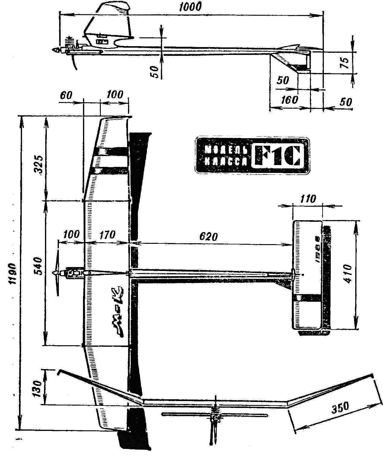
A good timer with an enlarged shoulder stabilizer was a very “fly” and sustainable in all modes. Therefore, our future plans include building an exact counterpart, only recalculated under the engine working volume of 2.5 cm3 . Sure that the benefits found scheme will also benefit the championship techniques of young athletes.
A. ALESHIN
Recommend to read ARSENAL HALT I want to share with readers his small devices, providing added convenience in the organization of the fire in camp during a weekend trek or a trip to his native land. One of the common... NORTH AMERICAN F-86 SABRE Aviation and missile firm North American (USA) has been building aircraft since 1934. During the Second world war, the firm produced about 42 700 aircraft, among which were such... 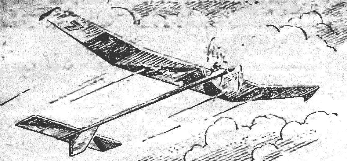
 The first year guys of our circle are doing Svobodnoye. Young athletes usppi to accumulate a lot of experience in the construction of light-winged paritala different classes and their application in the competition. The only time “school” class engines working volume of 1.5 cm3 was DPJ us a kind of a stumbling block. What depot!