Among novice modelers-korovikov argued that in the manufacture of teaching models overly bother not worth it — still the aircraft destined to endure at best a couple of flights. Well, can’t argue with that: indeed, clumsy, carelessly made and poorly assembled control line plane finished its flying service at times on the first laps on the track.
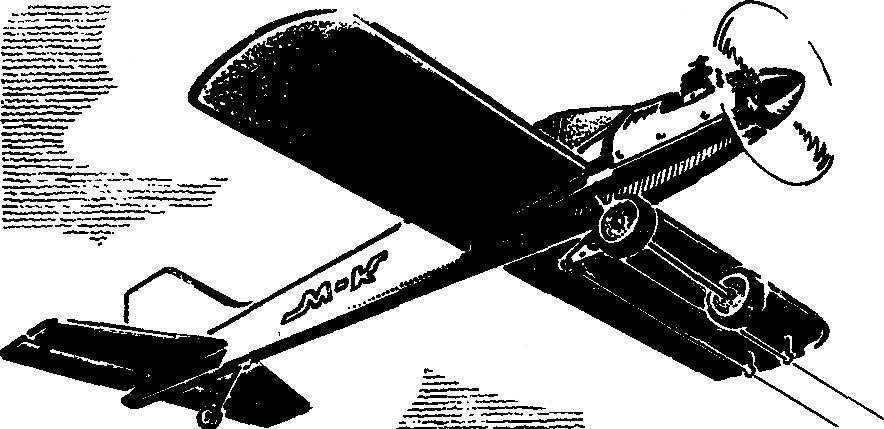
We offer beginner modelers is very simple and at the same time, enough flying, rugged aircraft, with a very attractive appearance polyopia modern sport aircraft.
The power plant model is a compression engine with a working volume of 2.5 cm3 type “MARZ” MK-12V or KMD-2,5. Suitable polutorametrovy MK-17 “Junior”; however, it will have to be especially careful to monitor the mass of the model so that its flight properties to maintain at an acceptable level.
The fuselage of the model combined. The front of it carved from lime wood thickness of 12 mm, and the rear is a flat stacked I-beam construction, glued top and bottom spars (pine slats section 5X12 mm), vertical posts (pine slats with a cross section of 3X12 mm), and braces (also pine strips 3X12 mm). Please note that vertical uprights and braces can be cut, in particular, from an ordinary school ruler. The connection of the parts of the fuselage is best done in the simplest slipway, which is a flat Board, on which is laid a sheet of paper with the applied contour of the fuselage. On top of the drawing is overlaid and secured with plastic film, anti-adhesive drawing parts of the fuselage. The latter are fixed on the stocks with small nails hammered into a Board at the outside edge prasowego image. When the Assembly items are further pressed to each other with small nails. Gluing is done with epoxy.
Motor mount is integral with the fuselage, of course, after gluing. It is carved from beech or hornbeam slats section 12X18 mm. in Addition to epoxy adhesive, for fastening the bars to the front of the fuselage you will need two studs with thread M3, nut and washer. The engine is attached to Motorama four screws M2,5X20 mm with nuts and washers. Note that the axis of the motor is rotated by 2° to the outside Cordoba circle — it contributes to the tension cord. Fuel tank dimensions 20X30X35 mm soldered tin has the capacity of about 20 cm3 .
Wing — classic stacked design. Its longitudinal elements, two longitudinal members (lower and upper) — from pine slats with a cross-section 4X6 mm; socks from pine strips 10 X 10 mm and the trailing edge also from pine slats, its section — 5X20 mm. Cross members comprise ribs cut out of plywood with a thickness of 1-2 mm and ending. The last picture shows bead consisting of plywood plates that define the shape of the wing in the plan, and the plywood the same rails that provide rigidity to the wing tips. However, you can make and more simple endings, cutting them out of foam and paste over tissue paper in an aqueous emulsion of PVA.
For the wing Assembly is also desirable to use plasam flat Board of appropriate dimensions (with pasted on it by platovym drawing), covered with plastic wrap. Along the front and rear edges of the wing nail preferably smooth slats, between which and mount it. The grooves on the front and rear edges of the wings are sharpened to the width of a rib of the saw blade with a cloth. This operation preferably be carried out simultaneously on both parts, fixing them in a Vice. The gluing is performed on epoxy resin. After curing of the resin surface of the wing vyshkurivaetsya with emery paper pasted on a wooden block. Then the outer part of the wing (outside, of course, relative to the circular trajectory of the model) are fixed dvadtsatimetrovy load; between the shelves of the spar is glued in the boss for attaching the control arms of, and to the inner root rib reinforcing plate is attached — it set the direction for the transaction leash cord.
The horizontal tail model are also stacked. The frame is glued from pine slats with a cross-section 3X6 mm (the ribs of the stabilizer and rudder, the leading edge of the stabilizer and rear of the Elevator) and 3X10 mm (rear edge of front stabilizer and rudder). The hinge on which turns the wheel height, the easiest way to make nylon thread, “sew” “the eights” the wheel to a stationary part of the tail in the drawing of these four areas. You can, however, take a more complex, but less visible hinge from strips of nylon tape. For this a strip of construction paper glued narrow nylon ribbon (both sides), and then this workpiece is inserted into the groove on the front edge of the rudder and the rear stationary part of the horizontal tail. Fixation with epoxy glue.
Pylon rudder is cut from aluminum sheet of 1 mm thickness and fixed by rivets made of aluminum wire thickness of 1 mm.
The keel of the model consists of a frame made up of pine slats section 3X6 mm, covered with Mylar film. The rear part of the keel is bent in the external direction (relative to the flight circle), which increases the tension of the cord in flight. The dorsal fin is carved from lime plate thickness of 3 mm.
Landing gear are bent from wire brand OVS or 50KHFA with a diameter of about three millimeters. The foam wheels with a diameter of 50 mm and thickness 20 mm. In the center of the wheel glued sleeve, rolled brass foil, over stretched “tyre” is a rubber band cut from a Bicycle camera “Pupil”. On the front wheel is fixed with two soldered to the rod / washers.
Skid is also made of steel wire, its diameter 1.5 mm. If you let the weight crutch can be provided with a wheel carved from foam by type of fixed wheels.
Assembly model special difficulties is not. The engine is mounted on the mount with the screws (with thread M2,5 or M3, 20 mm long) and nuts with washers. The fuel tank is fixed also on Motorama four tiny screws or two M2 screws with nuts; with pipe carb tank is connected with polyvinyl cambrica. The wing is introduced into the notched hole cut in the forward fuselage, and fixed with two plywood plates with a thickness of 1…1.5 mm., the keel is inserted in grooves sawn in the upper longeron rear fuselage, and secured with epoxy glue. The horizontal tail is fixed between the plates, are cut out of plywood 1 mm thick and glued on the sides of the tail section.
Wire landing gear is mounted on the front part of the fuselage by means of two plates of sheet aluminum of 1 mm thickness, two M2 screws with a length of 20 mm and nuts with washers. Skid fixed with fabric lining and epoxy glue. The engine is closed by a hood cut from an aluminum sheet with a thickness of 1 mm.
The slinky model is a Mylar film using glue BF-2 and electric iron technology is described in the journal “modelist-Konstruktor”. After covering on the wing is fixed to the rocking control and two guides for leash cord. Rocking control connects to the horn on the Elevator with a steel needle with a diameter of 1.5 mm or dural needle with a diameter of 2.5…3 mm. In conclusion, front (not covered with film) part of the fuselage is painted with alkyd enamel; the black and silver paint depicted as “the canopy pilot” — and the model can be sent to first flight. It can run on a 15-meter cords with a thickness of 0.3 mm.
Training cord model:
1 — propeller (Ø 200 mm, step 150 mm), 2 — compression engine, 3 — hood (aluminum sheet of 0.3 mm thick), 4 — fuel tank (tinplate thickness 0.3 mm), 5 — upper longeron rear fuselage (pine section 5X12 mm), 6 — vertical stand (pine section 3X12 mm), 7 — brace (pine rail section 3X12 mm), 8 — the front edge of the keel (pine section 3X6 mm), 9 — rib keel (pine section 3X6 mm), 10 — pylon rudder (aluminium sheet of 1 mm thickness), 11 — tail wheel, 12 — skid (OVS wire Ø 1,5 mm), 13 — pull rudder (steel needle Ø 1.5 mm or dural — Ø 2,5…3 mm), 14 — lower longerons of the rear fuselage (pine section 5X12 mm) 15 — the front part of the fuselage (lime plate thickness 12 mm) 16 — engine mount (beech or hornbeam sticks a cross section of 12 × 18 mm), 17 — rocking control (duralumin sheet thickness 1,5…2 mm), 18 — landing gear (wire grade 50 HPA or OBC Ø 3 mm), 19 — main wheel 20 to the front edge of the wing (pine rail with cross section 10X10 mm), 21 — rib (plywood thickness 1…2 mm), 22 — boss under a rocking chair administration (Lipa), 23 — boss under the guide ring, 24 — dvukhpolosnykh spar (pine section 4X6 mm), The 25 trailing edge of the wing (pine rail section 5X20 mm) 26 a load weighing 20 g, 27 — ending (plywood with a thickness of 1…2 mm), 28 — the leading edge of the horizontal tail (pine section 3X6 mm), 29 — rib (pine section 3X6 mm), 30 — trailing edge (pine section 3X10 mm), 31 in the trailing edge of the Elevator (pine section 3X6 mm), 32 — rib (pine section 3X6 mm), 33 — the front edge of the Elevator (pine section 3X10 mm), 34 — plate (plywood with a thickness of 1…1.5 mm), 35 loop (nylon yarn).
Recommend to read HOME MACHINE-TRACTOR STATION Since childhood read "modelist-Konstruktor" — he learned a lot of interesting technical ideas and developments. According to publications in the journal while still in school, redid the... “HOME” FOR MAGAZINES On my shelf is a... a five-story "house" and "live" in this compact tape cassettes. Grasp the ring on the roof, I can pick it up and put in front of him. Ring the top of the spindle,... 
 Among novice modelers-korovikov argued that in the manufacture of teaching models overly bother not worth it — still the aircraft destined to endure at best a couple of flights. Well, can’t argue with that: indeed, clumsy, carelessly made and poorly assembled control line plane finished its flying service at times on the first laps on the track.