Torque is transmitted from the output shaft of the chain drive sprocket; It is made from the hub — the old sprocket from the motor scooter “Vyatka”, the teeth of which are ground off up to Ø 34 mm, and destinului sprocket with Central hole Ø 30 mm. Between itself they are welded, as shown in figure 4.
Assembled tillers small. To further reduce its size, a regular muffler engine motor scooter was replaced with a homemade, more compact (Fig. 13) and on quality of work not inferior to those in the factory. For its production used a piece of muffler “Vyatka” — pipe with a garter belt. It is inserted in a glass Ø 75 and 65 mm in height and connected to the ring by welding. The glass is drilled a hole for the exit of exhaust gases. The silencer is fitted directly on the exhaust hole of the engine cylinder.
Engine starts like on the Vespa, kick. Fuel to the carburetor is fed by gravity. Gear shift is a lever that is welded to the sector gear box.
However, the basic controls are walk-behind — throttles and clutch — displayed on the control knobs of the hinged steering device and a cargo truck.
The bridge of the cultivator shown in figure 6. To install the overrunning clutches the gear shaft had to be lengthened by 170 mm (left and right 100 mm by 70 mm). For this purpose in the ends of the drilled Central hole Ø 8 and a depth of 30 mm and tapped M10. There I screwed the rods 130 and 100 mm, welded them to the shaft, bored through to a diameter of 25 mm and cut at the ends of the M20 thread length 40 mm Drilled hole Ø 3.2 mm under the cotter pins.
On the left end of the shaft mounted on a common keyway driven sprocket with 44 teeth and the leading part of the left freewheel (for this seat it bored through to Ø 35,5 mm and profesionaly keyway). The same groove made right on the shaft. Slave of the clutches is not altered, only I drilled new holes for attaching wheel discs from the cultivator.
Of course, if desired it would be possible to make a new chassis the shaft, it is shown in figure 7.
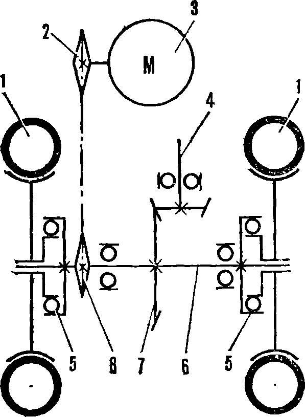
Overrunning clutch (Fig. 8) works as follows. When the shaft rotates, the leading part of your cells, rests on the driven roller and causes it to rotate. When turning the walk-behind wheel, moving in a circle of larger radius, rotates faster than the shaft, and the driving part of the clutch, respectively, faster slave. Therefore, the rollers compressing the springs slip at the cellular surface (she could hear the soft clicks). By reducing the speed of rotation of the rollers engage again with cells.
In the inner cavity of the slave portion of each overrunning clutch is pressed nylon bushing. The pair “running the shaft—Bush” lubricated with grease using a grease gun.
For the attachment of the device (Fig. 9) used by the nodes of the cultivator. Dual thrust shortened and welded to a connecting channel. It is done by the longitudinal holes for fixing to the tillers.
Fig. 9. Mountable device:
1 — connecting channel, 2, 3 — pipe handles, 4 — thrust 5 — rivet, 6 — holder bracket equipment, 7 — locking screw, 8 — hole mating with the frame of the cultivator, 9, 10 — jumper.
Fig. 10. The back of the truck:
1 — corner frame, 2 — side cladding, 3, 6 — loop fasteners to the frame of the truck, 4 — supporting area, 5 — bottom.
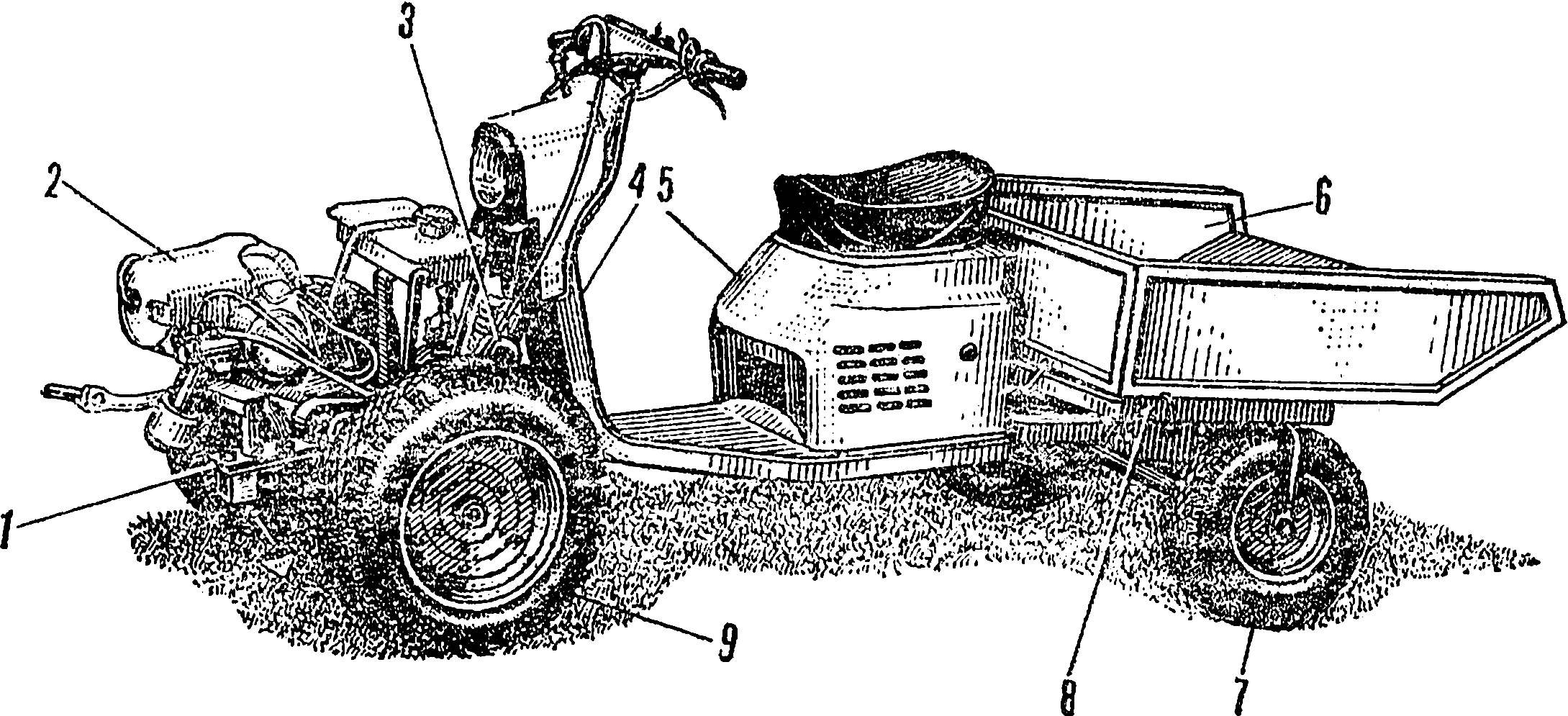
Fig. 11. Bogie frame:
1 — frame Vespa 2 — stud-seat, 3 — frame, 4, 7 — bushing hinge body 5 — additional angles 35X35 mm, 6 — pipe of the subframe, 8 — adjusting plate, 9 — remote part of the body of the scooter 10 — plug wheel, 11 — the emphasis of the housing of the brake drum, a 12 — lever-latch, 13 — lug, 14 — spring 15 — a guide bushing.
Fig. 12. Hinge joint:
1 — channel, 2 — holes for mounting to the frame of the motor-block, 3 — plate, 4 — spider, 5 — oiler, 6 — plug, 7 is shortening the steering shaft, 8 — ball bearings.
Fig. 13. Muffler:
1 — pipe with a garter belt, 2 — ring, 3 — Cup, 4 — reflector, 5 — exhaust outlet, 6 — bracket, reflector, 7 — optional loop fasteners.
End thrust bracket—holder of the equipment with the hole for the racks and the retaining screw.
The top channel is welded to the tube knobs. Their ends flattened and drilled holes for installation steering levers and accelerator and clutch.
Hinge joint (Fig. 12) made of a steering shaft of a scooter. Shaft shortened to 460 mm, and the bottom plug is welded to it the hinge of the automotive driveline. Return the plug is removed, and the ends of the crosses worn and welded them to the plate with a length of 135 mm. the Lower ends of the plates are beveled and welded to the channel. The latter also done longitudinal holes for mounting the truck to the frame of the cultivator. Lubricated hinge joint using a grease gun.
Based on the bogie frame (Fig. 11) — the frame of the motor scooter “Vyatka” or “Electron”. Below it is welded two angle 35X35 mm with a length of 870 mm. Rear free ends of them are connected by a third area with a length of 500 mm. Here the two plugs from the front suspension “Vyatka” (on the right welded the emphasis of the housing of the brake drum of the wheels), connected by a horizontal half-inch pipe. To her and to the main frame of the scooter is welded to another U-shaped sub-frame from the corner of 35X35 mm. For mounting the body to a horizontal pipe connected the two sleeve hitch.
On the transverse area of the sub-frame has a simple locking mechanism body: lever-latch, lug, spring and guide bushing. At a distance of 190 mm from the lever-lock drilled hole Ø 2.5 mm and inserted the cotter pin, which rests on the spring. In operating position the lock with its tip enters the front loop fastener of the body and holds it.
The body frame of the trolley (Fig. 10) made from the corners of 20X20 mm and covered with sheet steel 1.5 mm thick. it is welded to the Front loop of the fixing body in the transport position, and laterally — loop connection with the sleeve hitch where the fingers are inserted into the‘ steel rods Ø 17 mm.
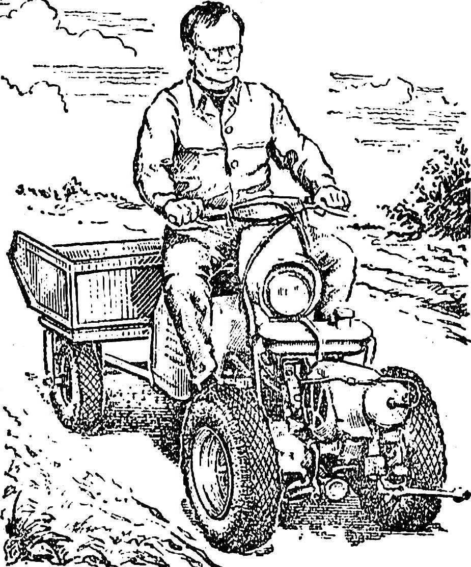
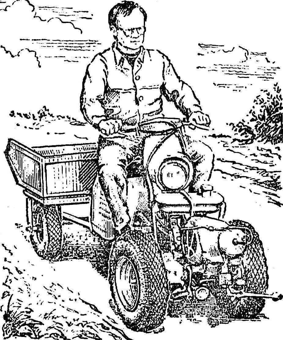
In conclusion, it remains to say that to control the tillers just. The members of our circle are, for example, mastering in one session. Convenient walk-behind and for the carriage of goods. The driver is shortened and expanded by 180° seat (with tool box under it) and controls the motor-block, holding a staff pen, left on the wheel.
Technical specifications of walking tractor
Length, mm: 900
Width, mm: 670
Height, mm: 900
Weight, kg: 65
Maximum speed, km/h: 18
Track, mm: 550
Track trailer truck, mm: 750
The base of the tillers with trolley, mm: 1580
The minimum turning radius walk-behind cart, mm: 200
V. NIKITYUK, head of the society
Recommend to read BELOKAMENNAYA YACHT A greater number of young athletes to the runaway yacht class P-2. And it is clear. The accessibility and speed of production, opportunities to experiment give the appeal of a "Junior"... FEEDING BY… PHONE Aquarists are often literally confined to the house: indeed, even for a few days can't leave the fish without food. Meanwhile, feed the fish and you can remotely, via an ordinary house...