Finishing and painting the forward fuselage — normal. In addition to simplicity, this finish will provide the notched part and greater reliability to protect the structure from the impregnation with fuel.
The CHASSIS is intentionally not shown in the drawings. The fact that he tested various arrangements of wheels and racks, and they all gave satisfactory results at take-off and landing characteristics. Therefore, the chassis can be constructed to your liking. This can be a simple wire clip, normal wheeled chassis with a rack out of sheet aluminum or wire. The massive nose section of the fuselage allows you to mount any of them. For beginners we can recommend the two-wheeled option with racks of wire, installed on the wing. This scheme will provide the easiest and most reliable takeoff. Strength same telefonerna wing enough to withstand the impact from the stands at the rough landing. Tail skid from wire Ø 1.8 mm privertyvaetsja to the fuselage with one screw M2,5 and the junction of poured epoxy.
ROTOR GROUP deserves special discussion. High-speed built under KMD-2,5 and under the modern “Rhythm”. B the first embodiment, the modifications undergone only the propeller, the engine in the upper left of the tripod mount of the rear wall is mounted a fitting selection pressure sverlova inclined holes Ø 1 mm, extends under the cylinder liner.
Those who want to achieve high results with the “Rhythm” of the modern sample, will have to thoroughly work with this engine. The first thing to take away Carter without cracking legs and a good tight fit of the bearings of the crankshaft. If the fit loose, like on most engines “Rhythm”, we can recommend sealing the indigenous ball-resin mixed with aluminum powder. The timing greatly expanded by replacing the connecting rod shorter (and more reliable) “meteorology” and install the ring under the bottom end of the sleeve (you can use the compression ring from the piston engine “Comet”). Overlay threaded carb removed, the entrance hole in the rear wall zaproponowano, set the nozzle from the motor REGION or CSTOM. Using the files section of the window in the valve is significantly extended, fixed the benches in the intake tract are eliminated, ashleeee characteristic of series motors, overlap almost two-thirds of the lumen of the flow section of the carb that failed distribution window of the spool even at its largest opening.
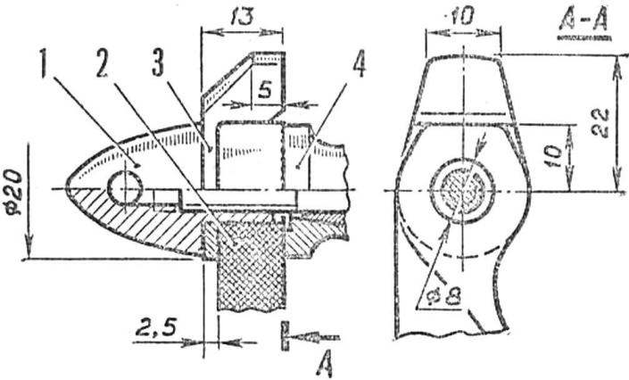
R and S. 6. The installation of a single blade of the propeller on the engine:
1 — Kok (hardened aluminum), 2 — blade propeller, 3 — counterweight (steel hardened, normalized), 4 — bearing bushing.
Fig. 7. Calculate the area of wing formed by the right quarter-ellipses.
The result of this work, mssh,the thrust of the engine increased significantly. Increased heat load that is demanded to improve the cooling of the cylinder (forced “Rhythms” were prone to “zadavlivanii” at the slightest overload). Careful analysis showed that the gap between the sleeve and the cooling jacket is unacceptable high, because of this so often encountered and primary of kontrpartiya to the mirror of the cylinder. Pick parts with desired landing failed even after bulkheads dozen motors. Reduce the same thermal resistance, we have achieved due to the introduction of aluminum strip. Taken from the engine casing neatly wrapped with foil (the gap between the edges of the tape about 1 mm, the combination is unacceptable, even with a double-layer winding) and quickly injected into the heated to 130-150°, greased shirt.
In any case, the engine worked with single-vane propellers, modified from serial plastic, 200X200 mm. To “Rhythm”, which develops maximum power at relatively low rpm, it is enough to shorten the blade to a radius of 90 mm without changing its geometry, KMD-2,5 work better with lightweight propellers. In addition to reducing the width of the blade, a significant amount of material removed and the top side of the screw, the profile is thinner. The balancer runs only from steel having a strength of at least 100 kg/mm2, the replacement of other materials and less durable steels is strictly prohibited! In the drawings, the sizes of the workpiece; more accurately they are selected after checking the balance of the propeller. After the balancing operation, it is necessary to perform another operation. It’s… again, it would seem to unbalance the finished screw! The radius of the blade decreases by 0.5—0.7 mm at its very end. This is necessary in order to provide the perfect balance in the output of the engine at maximum rpm. The fact that the nylon screws unlike wood and fiberglass have considerable elongation from centrifugal loads, a preliminary shortening of the blade allows to compensate the influence of the elasticity of the material.
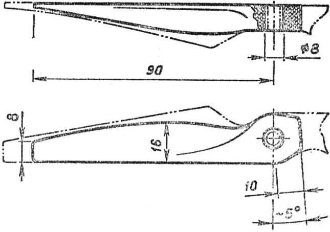
R and p. 8. Scheme revision serial nylon propeller 200X200 mm for engine KMD-2,5.
Fig. 9. Hinge rudder hinge (2 pieces):
1 — loop (semi-rigid wire Ø 0,8 mm, straightened paper clip). 2 — wrapping with cotton thread. Joints which are stuck in the holes at the ends of the Elevator and stabilizer to the epoxy resin.
The final step is determine whether to install keel. This element is deliberately not made in advance due to selection of its mass is easy to shift the center of gravity of the entire model to the desired position. Alignment speed should be within 10-15 mm from the front edge of the ventral section of the wing.
Before the first flight check again the lack of twists and loose all removable items. At takeoff speed behaves perfectly. Here a positive effect of its asymmetry, the center of gravity of the device in scope is exactly on the axis of the fuselage, the large separation of centre of area and centre of gravity provides a reliable stretch cords even at low speeds.
B. SOLOVIEV, candidate of master of sports
 “Wow, beautiful…” — that was the unanimous opinion of the participants about our high-speed cord models. After a short discussion, the boys made a “sentence” is a set of custom-making seem stamped out of plastic: “if we are…” oke We tried to explain that such models can build one that sets parcels elega/^tion speed is irrelevant and that make it much easier than any other… in Short, it ended up that I had to give details about the design, technology, construction and finishing of the new device. And then started flying again confirmed the unwritten law of aviation — a beautiful machine fly well!