When the design of the case was finally traced, it was nothing to design the pylon of the engine and the side float. Razzadorila young designers instantly “given” quite a good outline and etage a great prototype for the case of aerolister! Two slatted side rail connected to box beam plywood sidewalls — that is design that meets the requirements of minimum weight, high strength and stiffness, the availability of the starting materials. Any difficulties with the gouging of the workpiece, adjusting the translucency. Housing Assembly-I-beam is literally two nights. And most importantly — a solution allows to keep the scheme record of aeropittura, almost without increasing the total weight of the model.
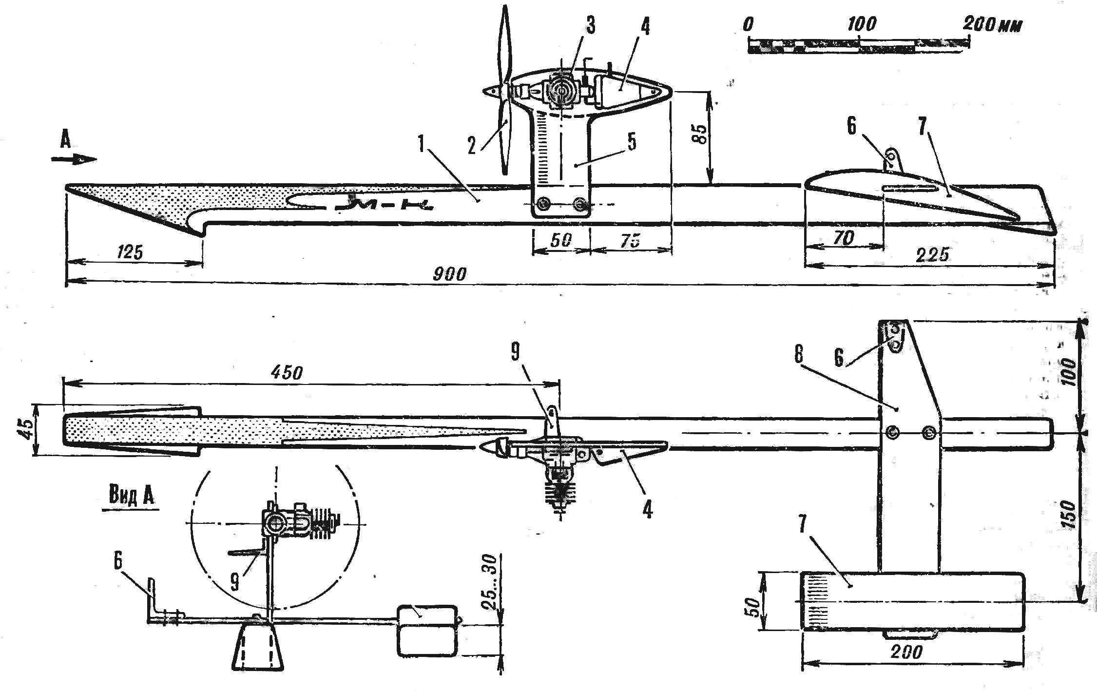
Fig. 2. Case design :
1 — sole nasal redan (D16T sheet of 0.5 mm), 2 — the base of the soles (pine, rail Х23 2,5 mm), 3 — solitaire of redan (Linden), 4, 7, 11 frames (plywood 2 mm, on the unaired portion of the housing frames are installed with a pitch of about 100 mm), 5 “spars” (pine, turnips 2,5×23 mm), 6 — side panel (plywood 1 mm), 8 — a lug of the pylon (birch, block 12 X 17 mm) 9 — M4 screws of fastening of the pylon 10 — M3 screws for fixing stabilizer, 12 — boss (birch, block 7 X 10 mm), 13 — feed redan (Linden), 14 — transom (Linden), 15 — spacer (the stroke 6 mm), 16 — strengthening of the joint (Linden, rail mounting 4 X 6.5 mm), 17 — fairing of the redan (Linden) 18 — wall (plywood 1 mm).
When the design of the case was finally traced, it was nothing to design the pylon of the engine and the side float. Razzadorila young designers instantly “given” quite a good outline and these
elements of the model. The pylon is hollow. He’s not less durable than telefonerna, but half the size. By construction, the lateral float is the same case, only plywood it will not in the sidewall, and the top and bottom of the hull. It weighs more than the chiselling of lime, and make it quality much easier. The only thing that failed, with relief of the stabilizer. Decided to just stick to the simplest option. Let the plate of two-millimeter plywood and has a minimum weight, but to cut it from the billet of the stabilizer, it only takes half an hour. A small increase in the total mass of the apparatus can be neglected
Fig. 3. Float :
1 — bulkhead 2 — wall (lip thickness of 2.5 mm), 3 — sheathing (plywood 1 mm fiber shirts across the patterns) .
The design of constant cross-section allowed to collect the body on a flat Board bench (on the side) unlike the hulls of canoes made of lime, having a rounded cross-sectional shape, are provided greater accuracy of Assembly, which ultimately is important for the sustainability of the model in the race. The Assembly were so. First on the stocks secured the plywood sheet on the right side and on his head like in the drawing, lecturing Reiki spars, the ribs and lugs, coated with epoxy resin. After curing of the resin the horizontal plane of junction with the left side cleared skin and to the frame at the same glue left sidewall. I had a straight, rigid in bending and torsion beam. I have a little round its longitudinal edges a few times to cover the body with waterproof varnishes and enamels and glue a sheet of aluminum foil on the bottom of the nose redan.
We have seen that the manufacture of the body in this way complicates the delineation of deepening under the pylon of the engine. Those who work with wood again, can do without this deepening, and pylon later to mount directly to the side of the hull. However, the appearance of the model and its resistance is deteriorated, but you can not be afraid of getting moisture inside the “beam”.
Fig. 4. The pole plant :
1 — base (plywood 3 mm), 2 — side panels (plywood 1.5 mm).
I must say a few words about the mounting system removable elements. At first the boys were going to put the screws without sealing, through and through. But then he realized that, and close up them firmly in the bosses will be able to get rid of the swelling of wood in places drilling and razbaltyvaniya threaded connections caused by vibrations of the engine. Now on all models we try to stick the screws in the lugs of solid wood. The cap is recessed into respective recesses, which further insures the screws from smoothbore stage casing, and the components better — it did not spoil the speakers head. The holes for the threaded part of the bolts is a smaller diameter. Carefully the screws are degreased and epoxy resin are screwed tightly into the boss. Before doing this it is useful to wait a quarter of an hour, the resin is pre-poured into the holes, is partially absorbed into the pores of the wood. After curing the epoxy loose threaded shanks are cleared through “run” it dies.
The manufacture and Assembly of the float is so simple that do not require further explanation. Billet stabilizer mounted in the slots of the walls of the float only after finishing the latter, then brought to the condition and the stabilizer.
Fig. 5. Fuel tank :
1 — supply pipe, 2 — wall, 3 — base, 4 — tube drainage and filling.
Established in our group the airboat was equipped with a Microdrive KMD-2.5 air screw d 160 mm increments 190-200 mm. requires Special attention to the preparation of the brackets hanging bridles. They should be absolutely rigid and reliable. Rear priklepyvayut to the right of the console stabilizer, front (main) is fixed with screws mounting the engine on the pylon. Methods of balancing conventional model, after specifying the size of the brackets hanging bridles the excess material cut off.
The first trial runs of the new device showed that the model is good: it is easily started, quickly went to treatment and did not seek to roll over after stopping the engine.
Weight of fully equipped glider without fuel — in the range of 400-450 g. We plan to equip the engine KMD-2.5 muffler from the engine “Talka 7”, is that will allow, without reducing capacity, to reduce noise to the required rules.
K. Lomov
Recommend to read “DREAM” — A CAR PRESCHOOLER Dream... How can she be the child? 1949. I am 5 years. Father Andrewski, the boy next door, buy somewhere a used pedal car (our industry at that time, in my opinion, not released),... ARMORED CAR IVECO UNDER THE BRAND NAME “LYNX” Cars, army UAZ-29661-vehicle with engine ZMZ-5143 98 HP and an elongated UAZ-2966 motor 9МЗ-4219.1 84 HP, which in the early 2000s were equipped with the Russian army, created on the... 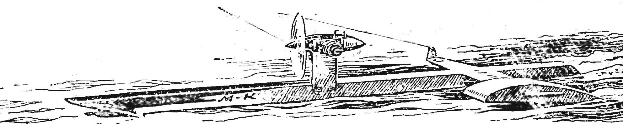
 Journal with drawings of Cordoba aerolizer who have developed a record speed, took all the guys from our club. “We will build these!” — without hesitation, they said. To dissuade the boys did not want, it is better not to do it when tempers flared. But the excitement gradually subsided. As usual classes were, and, trying to repeat superconstructor my players became a little “sour”. We have little idea the boy would have ended up with nothing…