But let us leave the theory alone. Importantly, found the scheme was affected by unusually promising. Tested on “basic” decisions and made after overflights insights so interesting that can serve as a basis for creating new, equally unusual vehicles many other aeromodelling classes.
But about this — later. But first — the story of the creation of a universal cord.
Three years ago, our group decided to prepare for the next urban youth competitions of the strongest fighters of the boys of Junior age. Immediately the question arose about the choice of equipment. After long discussions, stayed in combat, “Swift”, drawings of which were published in “M-K” No. 2, 1982. Attracted us above all the simplicity of this model, the ability to create a lightweight and durable design.
However, the finest “missile” Mylar film for covering the “Swift” to get failed. As usual, what is sold in stores, “Junior technician”, to use it was pointless to heat the tension would make an interesting model in “the beast” due to excessive retraction of soft rope edge.
And then decided to go the simple way. Rope edge was replaced with a flat rail, protecting it from the warp two light ribs. Refused Vyrypaeva using the templates of power of the front edge of it was replaced with pine wood. They also took over the functions and edges, and longitudinal, their ends carrying the bars, ending. To link the entire set in a single unit helped a plywood gusset plate. It turned out hard “impact-resistant” contour.
First flights on the new models with micro-motors “swift” 1.5 cm3 produced such good results that the members immediately began to build increased modification under the engines working volume of 2.5 cm3 . And here on these devices we have managed to solve a number of interesting questions. For three years built more than forty models, and each has served the new solution to creative problems.
Cord model under the engine 2.5 cm3 :
1 — the squared front edge of the spar (pine section 13X18 mm to the ends of the cross-section is reduced to 9X12 mm), 2 — vnutritrekovye wires management Ø 0,5 mm, 3 — solitaire Central ribs (plywood 1.5 mm), 4 — pad, increasing the thickness of the mounting wing under a removable engine mount dural to 28 mm (top and bottom, symmetrically), 5 — fuel tank capacity of 50-60 cm3 , 6 — spacer rib (pine 3X13 mm), 7 — strengthening of the joint (Linden or pine battens), 8 — solitaire ending (plywood 1 mm), at the intersection of the front edge of the external flap to stick with a lead weight with a mass of 10-15 g of 9 — ending (pine 9X10 mm), 10, 20 — gusset plate (plywood 2 mm), 11 — the rear edge of the pine (3X18 mm), 12 — Mylar film wing skin, 13 — the Central power rib (pine 7X13 mm), 14 — pull steering, 15 — Klondike output thrust from the cavity of the wing, 16 — pad (plywood 1 mm), 17 — butt tab (pine, 3 mm thick), 18 — “beam” (plywood 2.5—3 mm, seal in the notches in the Central ribs), 19 — all-moving stabilizer (3-4 mm plywood, cut Windows of relief, covered by Mylar film).
After the Assembly and installation of the engine model to be centred. Desired position of the center of gravity is at 23-25% of the MAR for all variants of the model (critical alignment — 27-28% of MAR). For this model the value of dimension “a” take in the range of 100 mm to high-powered engines to 125 mm for other variants and for low speed.
The basic data model
Bearing area, DM2 : 30
Full weight, g: 470
Specific load, g/DM2 : 15,6
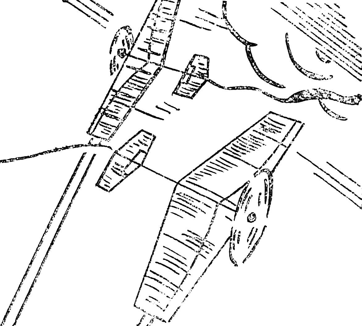
Assembly of the Central power unit frame (shown in mounting option of the rockers).
Before gluing to make a selection on the edge and the Central rib under plywood gusset plate, customized fuel tank. Glue based on epoxy resin under pressure simultaneously to glue tank. Elephant “shirt” plywood gussets — only along ribs. After curing of the adhesive edge of the scarf to security flush with the frame. In simplified models of scarves you can also make the frame.
Joint Assembly of the edge with the ending.
The conditions for executing transactions is similar to the Assembly of the Central power unit frame. “Shirt” — 45°.
Simplified joint edges with ending using a false gusset plate out of plywood with a thickness of 2.5 — 3 mm. Layers “shirt” scarves under 45° to the rails.
At the first stage investigated the effect of the thickness of the wing-plates on the behavior of bizovac in the air. At the same profiled edges all fly virtually the same: the only difference in the demands for the absence of random nevirapine twist in the wing. But when began the search for the optimal cross-section edges, realized depends on it, and handling the model and its sensitivity to wind gusts, and a tendency to drag on a sharp evolutions.
Now the guys are already used to evaluate models primarily in the form of the leading edge. Maybe this criterion is faultless, not in a hundred cases out of a hundred, but built in a mug apparatus stubbornly convinced us one thing: blunt, and even more is made along the radius in the entire thickness of the profile is no good. With him cord flies like she’s on the tail, as we say in circle, “the crocodile hangs”. In managing this model is sluggish, “stupid”, it responds to the impulses the weakening of the tension cord, the speed at the horizon is reduced, the slowdown in the figures significant.
When it was determined the optimal ratio between the height and length of the cross section of the leading edge, was left to wonder how many, without exaggeration, the famous designs are made without considering this important factor, how much improvement in handling properties are lost athletes!
The impact of profiling is especially pronounced on the wings, similar in cross section to the plate. Probably, it will affect, although not as much, and the flight profiles of the type. On the flat the wings the best results are obtained when the ratio of the length of the section edge to her height in the range of 1.5 to 2, provided that the wing has a semi-elliptical or close to a wedge shape.
Fuel tank:
1 — supply pipe of the engine, 2 — tin housing tank, 3 — tube filling and pressurization, 4 — bulkhead stiffness.
Control system:
1 — panel (solid wood glue between the gussets the power unit with the arm rocking), 2 — rocking bracket (made of anodized aluminum, the insert portion of the winding thread turn to turn), 3 — rod, 4 — “the castle” thrust, 5 — hog all-moving stabilizer, 6 — wires, 7 — rocking chair (made of anodized aluminum with a thickness of 2 mm).
Further work was aimed at creating durable, not having perepisany places design. And here we are faced with a new problem; how to clearly define a section of the rear edges. If the front take most of the load, the task back to close the power circuit of the frame and hold the film covering is taut. Many experiments have shown that when you rarely put the ribs enough to take care only about fulfilling the last condition. The first task will be provided automatically, and the calculation is not complicated with unnecessary operations.
The result was a chart-nomogram, which is easy given the amount of deflection of the edge under the influence of thermal shrinkage of the Mylar film is to find the minimum cross-section edges. We give it in full, knowing the capabilities of this graphics are fantastic. Of course, it’s not only the search of the dimensions of the parts to bouzouki. Simple to use, the nomogram allows you to create such designs, which yesterday did not have to dream! But we’ll cover that later. And the “lad camp”, according to the flight properties of superior balsa superparty.
Our teleconomy models share the same power circuit with bar-shaped edge spar and two spacer ribs. Frames was going solely on plasticized epoxy resin. Other glues unacceptable: the main circuit left the minimum number of nodes, so on each account for a significant load, and this work should be treated with the greatest care.
Another important factor is the choice of pine for the frame. So, for the rear edges best was the billet with layers parallel to the large side of the cross section edges. The same applies to the spacer ribs, and to the Central power. For all elements of the wing you should try to use grained wood. Its specific weight is not important: the simplified design has negligible mass.
Manufacturer model begins with the profiling of the workpiece leading edge. Then to her mate ending and the Central power rib. After curing epoxy liners endings cinch the twine, thereby set the deflection edge. As shown, in this way we can gather even frame without using any stocks. To bent “Luke” adjusted details of the rear edges and are Packed in it. After removing the twine, you can begin mounting the spacer ribs, scarves trailing edge and other parts. Ready frame is sanded with abrasive paper of different grits, promazyvayut glue and fitted by a conventional Mylar film with “podvorotni” with a width of about 10 mm.
On most models we have established micro-motors KMD-2,5 — dural Motorama profile of the area or on a traditional, carved out of plywood with a thickness of 10-15 mm. Food — under pressure the fuel tanks of conventional design, brazed tin-plated tin. It should be noted that even when using tanks, reduced in thickness to 10 mm, operation of the engine even on the most dramatic piece has deteriorated. Superfine Bucky is better to strengthen from within multiple end-to-end tubes-spacers or partitions. This will reduce the “game” of the walls when exposed to pulsating pressure from the crankcase. All elements of pattern tank run flare.
It should be noted that depicted in the figures, the model could be attractive to athletes-fighters. We have the same circle of the most popular lately won several other, larger sizes (it was shot on film). Swipe it from 1250 to 1300 mm, length of the root rib — 400 mm, end (endings) — up to 250 mm Shoulder stabilizer was increased to 100 mm, the dimensions of this node also increased (overall 100X400 mm). All-moving horizontal tail is fully compensated (the axis of rotation is at 24-25% of SAH stabilizer) and installed on a beam shooting from the birch bar.
We have experienced and other modifications. Training only pilots came model scale 1300 mm. Its advantage is the increased weight at low load, which allows you to confidently control the aircraft even at low speeds. Other option is even more: with the scale — 1500 mm, a length of the Central rib and 500 mm, wing area — up to 52 DM2 and load in the range of 12 g/DM2 . The model is very maneuverable. With a thin wing on the sharp pieces may have a strong twist, so the thickness of the “profile” it is better to increase to 20-25 mm.
Was built and the model of the other “extreme” reduced. Its basic data: wing area — 18, DM2 , stabilizer — 1.5 DM2 , the power scheme is the same, but with a fracture of the front edge toward the formation of the reverse sweep. Weight complete with original installed engine CSTOM-2,5 D 280 g (!).
In the previous issue we introduced you to unusual kordovye models intended for training of pilots-beginners and training “fighters” and the only pilots. Today talking about a more serious technique.
But to start, you need to first get acquainted with the schedule-a nomogram, allowing you to select the section edges.
Work with him. First of all, the drawing of the future of the model is determined by the maximum span of edges (m). Is then given by the maximum deflection of the edge (σ) that is valid for this model. For example, building a copy, based on the fact that the deflection of the edges do not need to be traceable and that the model will not fly for one year. In this case, stops on the permissible deflection of not more than 0.01 mm. In other models this size can be increased to 0.05 mm, such a deflection is almost unnoticeable. For game ask a deflection of 0.1 mm to 1 mm.
Nomogram for determination of deflections of the stringers and edges of the tension Mylar film 0.025 mm. Dashed line shows an example of use of chart. Received two edges that differ in mass two times.
The selected value is adjusted depending on the conditions. They are: the schedule is built for a conventional Mylar film with a thickness of 0.025 mm, plating single-sided, edge pine. If the thickness of the film available differ from the specified value of the specified deflection of the conditional increase proportionally (if more than a thin film) and Vice versa. In the calculation of the normal edge of the wing or tail that are affected by both sides of the trim plane, the value of σ respectively set smaller in two times, and the replacement of pine with balsa of the same section — four times. For example, when σ = 0.05 mm under a lightweight stabilizer to balsa edges with the film thickness to 0.005 mm after the correction setting σ = 0.03 mm.
Aerobatic model with modified engine “Rhythm” (from the wall KMD-2,5 and a new shirt of the cylinder).
Aerobatic model of the type “flying wing” with a modified engine “Rhythm”.
Aerobatic model with the engine a working volume of 7.0 cm3 . On the graph of lift coefficient against angle of attack illustrates a comparison of the aerodynamic characteristics of conventional stabilizer and stabilizer triangular low-aspect-ratio.
Then in the diagram through the selected point is carried out vertical to the intersection with the desired curve of the span m between the ribs (here you need to carefully check the conformity of the scales spans and deflections). Through this point spend a horizontal line on the right side of the chart. Any point of intersection with the branches of the right graphics will give the required combination of thickness and width edges. Will only have to choose the most convenient from the standpoint of binding to a specific design option.
Perhaps the first of these operations seem convoluted. But it’s worth a couple of times to take advantage of the charts and you will not be able to do without them when drawing each new model!
That can give the use of the proposed chart? To answer this question, take a look at the article accompanying drawings. They model excellent flight properties are achieved not only through the use of a familiar scheme, but also because of drastically reduced weight tail section, which can be achieved only when reasonable selection of cross-sections of the elements of their frames. Aerobatic engine “Rhythm” and all-moving stabilizer: the horizontal tail, made from only pine, after finishing and installing the hog weighs 12 grams! Model scheme “flying wing”: the Elevator in its finished form weighs 5 grams, the frame is pine! Large model with the engine a working volume of 7.0 cm3 total mass of engine… 580 g, all-moving stabilizer with a suspension unit and a horn after painting is only 12 g. This is much less accepted norms!
Naturally, the question arises: do we really need this?
The answer is simple — Yes! The mass of the tail part of flight or fighting, determining the moment of inertia of the whole model is almost the main variable influencing the most important handling characteristics. This ability to “walk” across the handle and generally perform a dramatic evolution. Any other techniques, in addition to reducing the moment of inertia, will not be able to make the flight pass angle of the “square” of radius less than 1 m, or fighting to make the “turn in place” without losing speed!
Confirmation of calculations and tests. Moreover, the calculations in contrast to the aerodynamic (in which corrections sometimes exceeds the desired value) is absolutely accurate and reliable, based on the laws of classical mechanics. And it is enough to “pump” any of known good models that after five minutes ‘ work with pencil and slide rule to understand: reserves of its improvement are still endless!
A. SOLOVIEV, club “Iskatel”, Moscow
Recommend to read STEERING THE MACHINE WITH THE MEMORY BLOCK It differs from steering devices based on electromagnets less weight, reliable fixation of steering, more traction and efficiency. The memory block machine provides a return of the... WHILE THERE ARE VINTAGE WATCHES… In other houses they are — big old clock in the wardrobe of polished red wood, with pendulum and two big shiny weights on chains. In those hours, something mysterious is through them as... 
 “No, this simply cannot be!” — these or similar words — “the standard reaction” athletes of any rank. And calls it the mention of flight models, three years under construction in our group. When the interlocutors know that this is not about celebarty superoperator, and about the training, though consisting of a dozen pine parts… then the faces can be read only undisguised distrust.