

 In most circles of technical simulation in our country now, unfortunately, no funds to purchase even the basic necessities, not to mention the purchase of kits for making teaching AIDS and models. Have to adapt, focusing on the use of industrial and domestic waste. But if a relatively simple design can still be built from “junk” materials, equipment remote control much more difficult.
Well, our club rescue is relatively inexpensive… RC toys foreign (mostly Chinese) production. Rather, what remains of them at home toy libraries have inquisitive children. Prevails, as a rule, broken mechanics, but with a proper remote controls (transmitters).
It turned out that all this equipment is assembled on repetitive schemes with the same encryption commands: when the control stick is in the neutral position, the transmitter is disabled and no signals are not transmitted anywhere. In any other case the signals are generated in the form of packs of 6 pulses with synchrophasing between them and a repetition period of 25 MS.
The first and sixth pulses here, apparently, the gate; the second is left, third is right; fourth with the movement back and the fifth — forward. The pulse duration of the unused commands is 0.5 MS, the duration of any following pause is 2 MS. Conversely, commands used, these parameters have values respectively of 2 and 0.5 MS. Moreover, the panel is arranged so that its mechanism does not allow simultaneous transmission of mutually exclusive commands FORWARD and backward, LEFT and RIGHT.
Based on experimentally updated data managed to develop a decoder, which allows to equip the input of members of the remote control using the toy transmitters. In its design, is available even to a schoolboy, just a couple capacitors and resistors and four chips are quite common series К561.
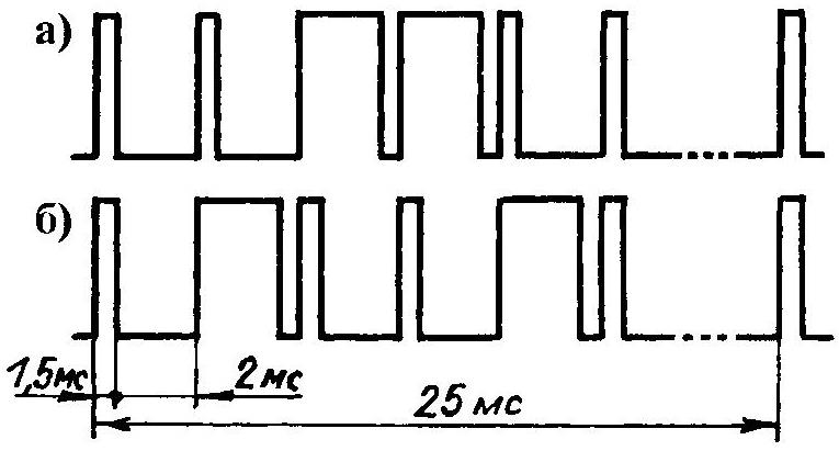
Timing diagram of command pulse to the RIGHT — BACK (a) and the LEFT — FORWARD (b), typical for electrified toy foreign (Chinese) production
Two one-shot for logic elements of microcircuits DD2 (K561LA7) are included in parallel. The rising edge of the negative “spike” coming from the receiver through the inverter DD1.1 and DD1.2 (K561LA7), the first one-shot (DD2.1, DD2.2) produces negative pulses with a duration 1 — 1.5 MS. His work depends on the values of the timing elements C1 and R1. The second one-shot (DD2.3, DD2.4), respectively, produces negative pulses with a duration of 15-20 MS. Define this duration, the values of C2 and R2.
Short clock pulses follow at the shift register DD3, long — on reset information in it and to write to the memory registers DD4. And remove from the inverter DD1.1 positive “pichok” is supplied to the information input 15 of the chip К561ИР2. So if the receiver comes with the unused momentum of the team, he is shorter than the clock coming from the one-shot on DD2.1 and DD2.2 (1.0 to 1.5 MS). So, in the shift register will be written to a logical “0” (low level). Conversely, if the impulse arrives commands, the device recognizes the “enemy” long clock. Accordingly, the shift register will be written to a logical “1” (high level).
After writing to the shift register of information about all six pulses will be synchropulse, during which a second one-shot on DD2.3 and DD2.4 generates a positive pulse.
The device will send information on the second, third, fourth and fifth pulses in the memory registers collected on the chip DD4 (К561ИР9), and reset the shift register is performed on MC DD3.
Strictly speaking, schematic diagram of the audio decoder should include an integrator, the purpose of which is to generate a reset pulse (cleaning) memory registers for DD4 after the termination of the receipt of the packets from the receiver, that he did not remember last team. That is exactly what was envisaged in the original version with additional logic elements in the composition of the K561LA7 (DD1). But in practice this proved unnecessary.
The fact that the receiver (it is made for the development, published in the journal “modelist-Konstruktor” No. 10 for the year 1989) to the decoder come inverted (negative) pulse packet. Upon termination of generation of the transmitter signal level at the output of the receiver immediately drops from a high (logical “1”) to low (logical “0”).
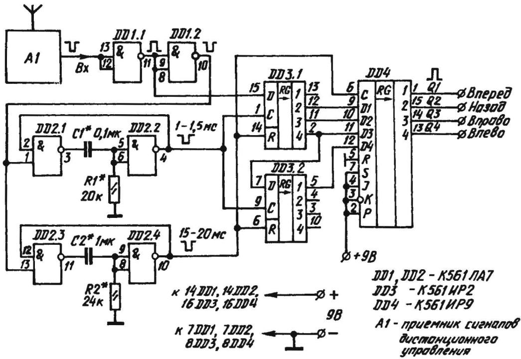
A circuit diagram of a self-made decoder of commands of radio control models using a toy transmitters

Circuit Board side solder electronic components (a) and the main printed conductors (6)
This differential trigger standby single vibrators, first the shift register is written to logic “1”. And as more pulses from the receiver already doesn’t arrive, 15-20 MS, the second one-shot generates the appropriate command or electronic memory DD4 recorded low levels (logical “0”). In other words, is self-cleaning memory registers.
The instruction decoder is assembled on the circuit Board of the bilateral foiled fiberglass dimensions 70x30x1,5 mm.
The Executive device can be very diverse. Especially if you use the same Pinout and standardized, conventionally not shown in the illustrations mini electrical connector.
Even greater versatility receives such equipment when placed in a common compact housing not only the receiver with the decoder, but also battery power (e.g., 9-volt “Crown”) with microswitch. Themselves actuator should be rigidly mounted on the model and to connect with the power source running the motor.
Vitaly SAVELYEV, head of ship modeling circle CDT, Raduzhny, Vladimir region
Recommend to read
 BICYCLE UNDER LOCK
A small piece of steel cable, sheathed in a tubular plastic cover, enters a metal cylinder smaller than a hockey puck at its ends. This is a bicycle lock designed to prevent theft. It... It will go out, but not immediately
One of the inconveniences in the design of many cars is that the interior light immediately turns off when the doors are closed. There are, of course, special devices that delay switching...
