AMPHIBIAN VYATKA STUDENTS

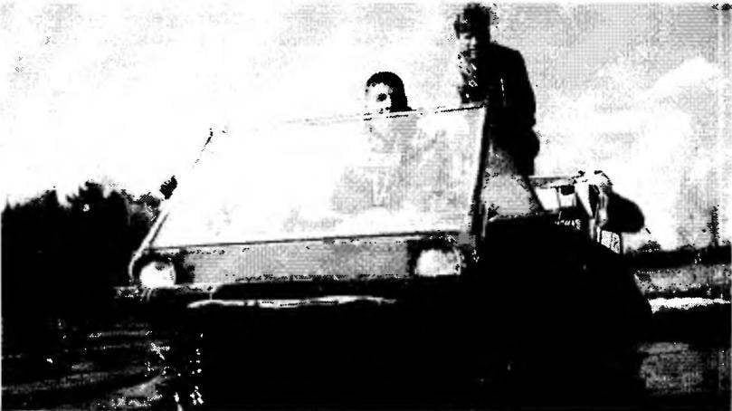
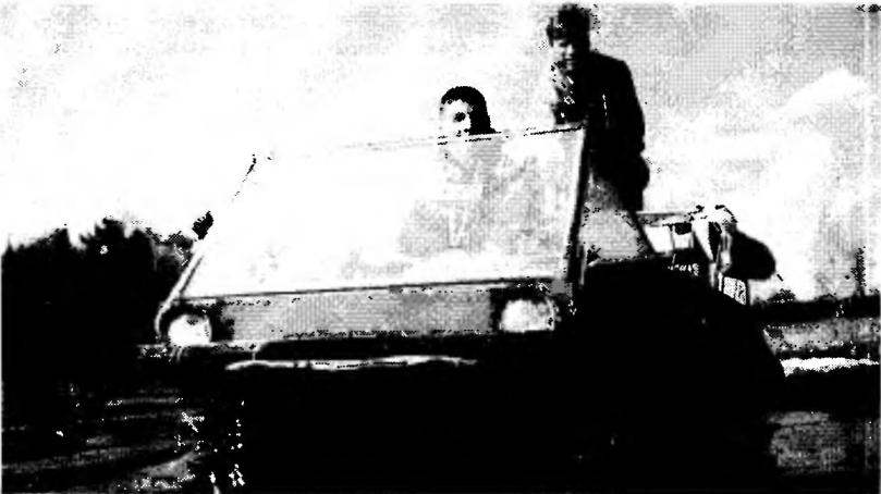
Off-road amphibious all-terrain vehicle tires low pressure, built studente and employees of technology and economic faculty of the Vyatka state pedagogical University, in operation for more than ten years. During this time, confirmed the unique capabilities of the machine. The Rover moves steadily along any road, through thick dirty, snowy or swampy terrain of the area covered by tussocks and shrubs, overcomes water obstacles. Its own mass of about 250 kg, can carry up to 500 kg of cargo on water and land.

The vehicle is made in wheel circuit 4×4. All its wheels are made manageable, which reduced the turning radius to 6 meters (with a smaller angle of rotation of the wheels).
 
Ahead of on the housing, a transparent plate (organic glass in a welded frame of steel area) that protects the driver from wind and rain and preventing the engulfing water of the cab while coming down the steep Bank into the river. With the same purpose, the forward part of the strongly extended forward and provided with a sealed cavity under the wings.
 
The open cabin (the driver’s seat and steering wheel in it a little offset to the left from the longitudinal axis of symmetry of the body) should be a cargo Bay, which, however, freely is and passenger. To protect driver and passenger from the elements can be mounted folding tent. The aft power unit, and above it — a roomy trunk, welded steel rod with a diameter of 8 mm (acceptable replacement in rented car).
In the design of the amphibian is used entirely powertrain motorized FDD — the engine, transmission, main transmission, wheel hubs, brakes (virtually unchanged). For front wheel drive the main gear.
 
Welded frame of the vehicle. Consists of two spars, beams front and rear axles, bent axles with bushings for mounting the steering knuckles of the wheels, the supports of the power unit and the pair of mounting brackets of the steering mechanism and front main gear.
 
Amphibious all-terrain vehicle
 
Amphibious all-terrain vehicle
 
The layout of the vehicle (overhead trunk and fuel tank is not shown)
 
The layout of the vehicle (overhead trunk and fuel tank is not shown):
 
1 — steering wheel; 2 — steering shaft (levers, accelerator and clutch conventionally not shown); 3 — gear steering; 4 — steering mechanism; 5 — wheel; 6 — the knuckle; 7: a frame of the vehicle; 8 — circuit front axle drive; 9 — reducer shaft, intermediate; 10 — transmission main, rear; 11 — bolt M10 anchoring the Rover to the housing (4 PCs); 12 — frame of the power unit; 13 — silencer; 14 — unit power; 15 — timing chain intermediate gear; 16 — the contour of the floor of the cargo compartment; 17 — body of the vehicle; 18 — the driver’s seat; 19 — thrust the front steering linkage; 20 — steering rack mechanism; 21 — earring; 22 — ball pin; 23 — plan-spacer wheel; 24 — stud wheels; 25 — liner foam; 26 — drive sprocket; 27 — spline coupler; 28 — a flange of the protective liner; 29 — axle shaft; 30 — cross; 31 —stocking protective; 32 — screw propeller; 33 — reducer propeller; 34 — chain drive gearbox propeller; 35 — a gear lever shaft, rear; 36 — bearing bracket with slide; a 37 — finger rear steering linkage; 38 — sleeve (bearing slide); 39 — knuckle; 40 — an intermediate shaft; 41 — gear shaft; 42 — a transmission main, front.


Frame vehicle
 
The frame of the Rover:
 
1 — bracket, steering gear mounting (steel, sheet s4. 2); 2 — mounting brackets the front of the gearbox (steel, sheet s4, x4); 3 — longitudinal (perforated channels, 2 PCs.); 4,5 — bearing engine; 6 — bushing mounting novorotor fist (pipe 36×8, 4-piece); 7 — axle (pipe 40×5, 4 items); 8 — beam front axle (tube 50×5); 9 — bolts M10 (8 PCs); 10 — tie bar (30×30 area); 11 — rungs (30×30 area); 12 — Klondike (steel, sheet s5, 4 PCs); 13 — rear axle beam (tube 50×5).

 
Examples of compounds of the elements of the case
 
Examples of compounds of the elements of the case:
 
1 —Board (plywood s8… 10); 2 — screw; 3 — layers of fiberglass; 4 — holes (Ø3, step 20 mm along the weld) to fill the epoxy resin; 5 — the bottom (plywood s8…10).
 
Steering knuckle (front right or rear left side, the mirrored view)

 
Steering knuckle (front right or rear left side, the mirrored view).
 
Node adjustment of the toe angle of the wheel
 
The node adjustment of the toe angle of wheels:
1 – pull the steering linkage; 2 – threaded bushing; 3 – nut; 4 – a tip.
 
 
Frame performs mainly a layout feature; the stiffness and strength of the whole structure of the Rover attached to its body connected to the frame with four bolts M10, although he has no power set. Its panels are made of carved plywood with a thickness of 8-10 mm and assembled with screws 4×25 and epoxy resin. Then the butt edges of the panels are drilled with a step of 20 mm to ensure that the glue has penetrated in the hole and stood there like nails, and plastered on both sides with strips of fibreglass on the epoxy in 2-3 layers. After that the body was entirely covered with two layers of glass “epoxy”. In the last layer of resin added to the pigment and aluminum powder.
 
Interestingly, in our view, solved the problem of sealing the housing at the exit points of bridges. The openings in the housing surrounded by rings of aluminum with rubber corner pads. To these rings by the same rings of slightly larger diameter screws M5 attached wide stockings made of rubberized fabric. The other end of the stockings attached to the brake shields, wheel clamps made of profiled steel tape. The stockings are made with a stock length so the wheels could turn in the required limits.
 
Thus, the entire drivetrain, powertrain and other systems were well insulated from water, dust and dirt, which significantly increased their resource and reliability. Significantly increased and a displacement hull for amphibians is important.
 
In the control system of the Rover used steering gear, steering wheel and shaft with the levers of the throttle and clutch from FDD (manual control of such a car seems more convenient). Steering gear, linkage steering linkage and the steering knuckles of the wheels — own design.
 
Each steering knuckle is cut from Stalnoy plate thickness of 10 mm. In the workpiece drilled otwarte under the wheel hub and bolts of its fastening. Then it is welded coaxially to the sleeve and the lever with the hole for the ball stud. With these bushings and king pin steering knuckle is pivotally attached to the axle frame.
 
In this design the maximum turn of the wheels leads to some change (within 10 mm) of the distance between the ends of the axle and the shaft of the main transmission, which is quite acceptable and kompensiruet regular spline coupling of the drive. By the way, the Rover used four of the leading hub (rear) wheels of the FDD.
 
Thrust steering trapezoids from a steel pipe diameter of 25 mm, the ends of which are screw-in lugs with lock nuts, allowing you to adjust the angles of toe. Pull the front steering linkage is driven through it is welded to the stud and the ball stud directly from the gear rack of the steering mechanism.
 
To control the rear wheels front and rear steering trapezoid gear shaft is connected with the levers at the ends. The shaft turns in sliding bearings, mounted on the right frame spar. Leverage through the sleeve pivotally connected with the fingers welded to the steering tie rods. So simultaneous rotation of front and rear wheels in different directions. The design appears to us more simple and compact compared with a system of levers, pendulum poles and rods used in such cases.

 
The layout of the vehicle is such that the axis of the steering shaft and the steering mechanism was at an angle of 60°. So I had to make a gearbox with two bevel gear wheels disposed in the housing of aluminum alloy. The reducer attached to the body of the vehicle by two brackets made of sheet steel 3 mm thick.
 
To reduce the frequency of rotation of the large diameter of the wheels and torque the power unit is equipped with an intermediate shaft providing a gear ratio of about two. Used a slightly modified intermediate shaft from a walk-behind tractor with one sprocket z = 21 and two — z = 11. The tubular shaft rotates in needle bearings on the axis, which is fixedly mounted in the holes of the cheeks, fastened to the frame of the power unit in the mounting locations of the main transmission.
 
The intermediate shaft is driven in rotation by a chain from the drive sprocket transmission output shaft. Also chains the intermediate shaft is connected to the primary shaft sprockets front and rear main gear (primary shaft before it was inverted, which was easy to do because of their symmetry).
 
The distance between the axes of the intermediate and input shaft front main gear is about 900 mm. Requires the chain tension to avoid sagging and contact with the housing. The tension is due to the deviation of the power unit on an elastic suspension with a sliding rod (not shown).
In the process of operation of the vehicle revealed that regular rubber clutch rod FDD not strong enough and quickly fail. In addition, their elasticity is much increased effort on the steering wheel necessary for steering the machine. So they were replaced with universal joints (crosses) from the UAZ. The axle shaft and splined couplings — FDD, their ends trimmed and welded plugs u-joints.
 
The design of the transmission can include separate front and rear axles. Experience has shown that the need for their simultaneous operation is quite rare: usually on the particularly difficult parts — when leaving the water, driving on high bumps and so on. However, on such modes possible the rapid accumulation of difference of front and rear wheels due to the difference of their sizes, air pressure, and irregular rotation on an uneven surface, which leads to excessive stresses in the transmission due to the “circulation of power”. It is fraught with rupture of the chains, the breakage of the gears in gearboxes, and even the destruction of their buildings (all of this happened).
 
To prevent these phenomena, the mechanism for the inclusion of a forward gear of the main transmission rear axle has been modified. The back, outside part of the Cam gear forward clutch and a Cam included in engagement with each other, was filmed on the sandpaper at a 45° angle. Thus, in the event of a reverse torque on the wheels the gear now, or is automatically put into neutral or turns into a one-way clutch.
 
Know how the differential lock increases the permeability of the vehicle in difficult conditions. In our case this is particularly important when leaving the water and driving through the snow. However, to provide a lock of the regular differential main gear FDD without major alterations is not possible. An easier way is to turn the differential in the one-way clutch. To do this, seven of the ten teeth of each pinion have been ground off on the sandpaper; a hollow between two of the three remaining filled with molten metal with the help of electric welding; and the satellites are spring-loaded on your finger, turned into the dogs of the ratchet mechanism, each for their own side gears. Hence, the free rotation of the side gears faster box (Cup) differential (when entering, for example, the outside wheels in a turn), the synchronous rotation of the wheels and high flotation on bezdorozhe when driving straight ahead and when you slipping. And in the end, a satisfactory control of the vehicle.
 
The disadvantage of this method of “blocking” — the inability to use the front axle in reverse (we have a front main transmission reverse gear removed), but the advantage still more.
 
An important part of these machines — wheels and tires, because they provide them an increased permeability. The lack of suitable wheels industrial production makes Amateur designers find their way.
 
Our wheels is aluminum cans with a diameter of 450 mm. I Must say that they are made from a fairly thick sheet (2 mm). Now on sale more often a thin (1 mm), they are only suitable for use for its intended purpose. The discs among themselves and with internal plan goals of duralumin sheet thickness of 5 mm are bonded with five M8 screws, hubs FDD they pulled four extra long nuts.
 
 
The theoretical contours of the body of the Rover
 
The unit of connection of a trapezoid with the front gear shaft (top view)
 
The connection node of the trapezoid with the front gear shaft (top view):
 
1 — pull the steering linkage (pipe 25×2); 2 — shaft transmission (pipe 20×2); 3 — earring; 4 — rubber sleeve; 5 — the lever shaft; 6 — toes M8.
 
Steering gearbox

 
Steering gearbox:
 
1 — housing (aluminium); 2 — the adjusting washer (brass); 3 — bushing (brass); 4 — gear shaft (steel).
 
Right bracket steering gear

 
The right arm of steering gearbox mounting (left side mirrored).
 
The details of the mechanism of inclusion forward in the main transmission rear axle with cut off under 45° outside hakami (shaded)
 
The details of the mechanism of inclusion forward in the main transmission rear axle with cut off under 45° outside hakami (shaded):
 
A — pinion gear forward gear; B — coupling of the Cam.


Modified differential gear of the front axle
 
A modified differential gear of the front axle:
 
1 — satellites with three left (out of ten) teeth and deposits (shaded); 2 — thumb; 3 — gear rod; 4 — spring; 5 — M5 screw mounting of the spring.
 
Intermediate shaft chain gear
 
 
Intermediate shaft chain gear:
 
1 — asterisk is large (z= 21); 2,5 — small sprocket (z = 11); 3 — intermediate shaft (pipe 32×2,5); 4 — spacer (pipe 27х 1,5); 6 — the needle bearing in the yoke (2); 7 — thrust washer (bronze, 2 pieces); 8 — cheek (2); 9 — axle; 10 — oiler.
 
Reducer propeller

 
Gearbox propeller:
 
1 — bushing sprocket; 2 — star (z = 21); 3 — cover screw (М50х 1,5); 4 — bearings 204; 5 — nut shaped M20; 6 — shaft-gear; 7 — gear, full-time; 8 — an arm of fastening of a reducer; 9 — driven shaft; 10 — rivet (steel, Ø5); 11 — housing; 12 — head.


The strength of such discs is sufficient for the operation of the vehicle under normal conditions. However, careless driving on stumps, high hummocks and fallen trees, while overcoming the deep ditches with overclocking and so on such discs sometimes crushed, usually from the outside. So we strengthened them foam liners with a thickness of 100 mm. Ear firmly pressed to the external drives the plan-washers of 3 mm thickness and nuts screwed onto studs that are inserted into the elongated wheel nuts. In addition, foam increases buoyancy and stability of the vehicle on water.
 
Tires low pressure — double chamber size 900×300 mm, end-of the resource in the wheels of the aircraft. External camera cut to the interior diameter and attached to the disk M8 screws with spherical heads. For better traction, and size limits on external camera glued perforated conveyor belt.
 
Wide track and short wheel base of the vehicle, low pressure at wide thick tires (0,2*105 PA) can do even without the suspension, which greatly simplifies and facilitates the design of the machine. The only disadvantage associated with the lack of suspension and we discovered in the process of operation, longitudinal swinging (resonance) of the loaded vehicle at a speed of approximately 20 km/h. From this we removed, providing the trunk shock absorbers scooter.
 
For several years the vehicle was operated without the propeller moving through the water due to the rotation of the wheels. However, the speed of this motion was very small, especially with a headwind and waves. Not helped by the blades mounted on the lateral surface of the wheels. Currently, the vehicle has a propeller from the outboard motor “Whirlwind-20”, which is the drive chain from the shaft of the fan motor using a modified gear from the same “Vortex”. Revision of zakljucili in the manufacture of the new case and mounting bracket, the elongation of the driven shaft, install the shaft-gear bushing with an asterisk.
 
The new housing is welded from pieces of steel pipes of suitable diameters, treated with a size standard gear components. Special care required welding of the housing parts to each other and to the mounting bracket, to avoid warping.
 
Driven shaft lengthened by 250 mm with the nozzle, made in the regular dimensions of the shaft and connected to it by two steel rivets. The elongation required installation of additional support — ball bearing 204 fixed to the housing by a threaded cap with lip seal.
 
Torque from the engine shaft of the reducer is passed through the grommet with a square hole, made according to the size of standard gear shaft. The connection of the sprocket with the bushing welded. On the sleeve with the nut fixed ball bearing 204. Regulation of the gaps in gears and mount the drive shaft in the housing are the same screw-on cap with lip seal (for mounting in the sprocket holes).
 
The driver controls the gear from his seat with a lever having a fixed position “forward”, “neutral” and “back” cable wire key (not shown). Speed on water 5 km/HR, which is sufficient to overcome water obstacles even during resenih spills. When the land screw and chain drive can easily be removed.
 
Due to the installation of the reducer of the screw using the standard muffler motorized FDD has become difficult. Had to make a silencer out of pipe segments of different diameters. Case of pipes of 80 mm diameter with the ends sealed, the inlet and outlet pipes inside have 12 holes 8 mm in diameter. the Reduction in engine power is not seen, the noise level compared with the initial increased slightly.
 
V. MULTANOVSKIY, SEMENOVYKH, Kirov


Recommend to read

  • UMBRELLA — THE CASTLEUMBRELLA — THE CASTLE
    Do not rush to dispose of old tires from a moped or motorcycle, they can still come in handy. If you cut off a piece with a length of 60-90 mm and put it on the hitch lock, you get the...
  • Mil, Mi-24Mil, Mi-24
    The first flight of the new military troop transport helicopter, which later received the name Mi-24, was held on 15 September 1969, and in 1970, began its mass production. In the...